Holder combined with cradle for portable terminal

a portable terminal and stand technology, applied in the direction of machine supports, casings/cabinets/drawers, casings/cabinets/drawers details, etc., can solve the problems of difficult to adjust the holder devices according to the size of users' fingers or hands, and the terminal is easy to slip from the user's hand, etc., to achieve convenient and stable grip, enhance maneuverability, and expand the operable range

Active Publication Date: 2020-10-13
LEE KI BEOM
View PDF28 Cites 3 Cited by
  • Summary
  • Abstract
  • Description
  • Claims
  • Application Information

AI Technical Summary

Benefits of technology

[0016]According to the present disclosure, the size of the stand-holder is adjusted to an optimal size according to a size of a user's finger, and the back of user's hand is pressed by using the seesaw structure. Therefore, a user can operate the portable terminal while stably griping the portable terminal only with one hand regardless of the size of the portable terminal size.
[0017]In addition, according to the present disclosure, the support portion attached to the portable terminal is formed to have a predetermined thickness, and to support a tip of a finger. Therefore, a more comfortable and stable grip can be provided, and also, maneuverability can be enhanced when the user grips the portable terminal. In addition, there is an additional effect of enlarging an operable range.
[0018]In addition, according to the present disclosure, the folded state of the coupling member is automatically released by a one-touch operation, such that the user can easily wear. The front end of the holding portion is automatically supported on the rear surface of the portable terminal, such that a switchover between the function as a holder and the function as a stand can be rapidly performed without an additional operation.
[0019]In addition, according to the present disclosure, the size of the holding portion is enlarged, and stability can be enhanced when the stand-holder is used as a holder or stand.

Problems solved by technology

However, in the case of a large and thin portable terminal, it may be difficult to operate it with one hand, and also, the terminal is easy to slip from user's hand.
Therefore, users often drop portable terminals.
However, it is impossible to adjust the holder devices according to sizes of users' fingers or hands, and also, users may not have a good grip when holding the holder devices.
Therefore, there are problems that it is not easy to input texts or take pictures, and there is a limit to changing directions, and thus portability and maneuverability deteriorate.
However, the rod should be inserted into a deep position between fingers in order for the user to stably hold the portable device, and it is not easy to operate the portable device with one hand while holding it since the support plate is in contact with user's palm.
Therefore, when the user operates the portable device with user's thumb, holding is unstable, and it is not easy to operate the portable device with user's thumb when the portable device is stably held.
In addition, since the related-art technology requires a separate stand to stand the portable device on a floor surface at a predetermined angle, there is inconvenience in using.

Method used


Image

  • Holder combined with cradle for portable terminal
  • Holder combined with cradle for portable terminal
  • Holder combined with cradle for portable terminal

Examples


first embodiment

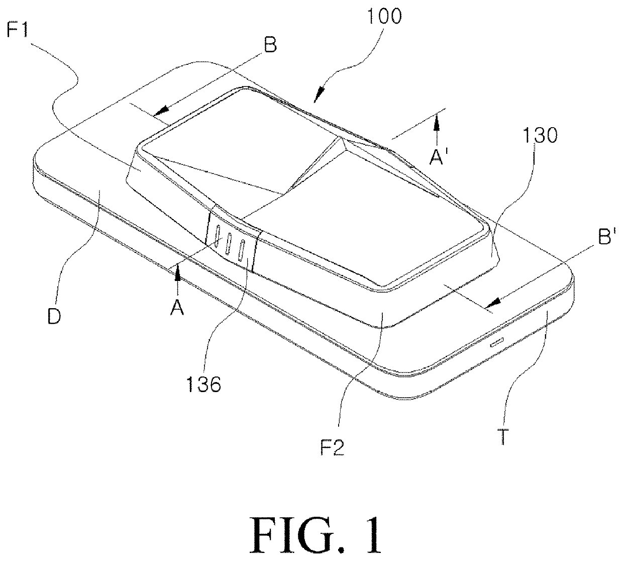
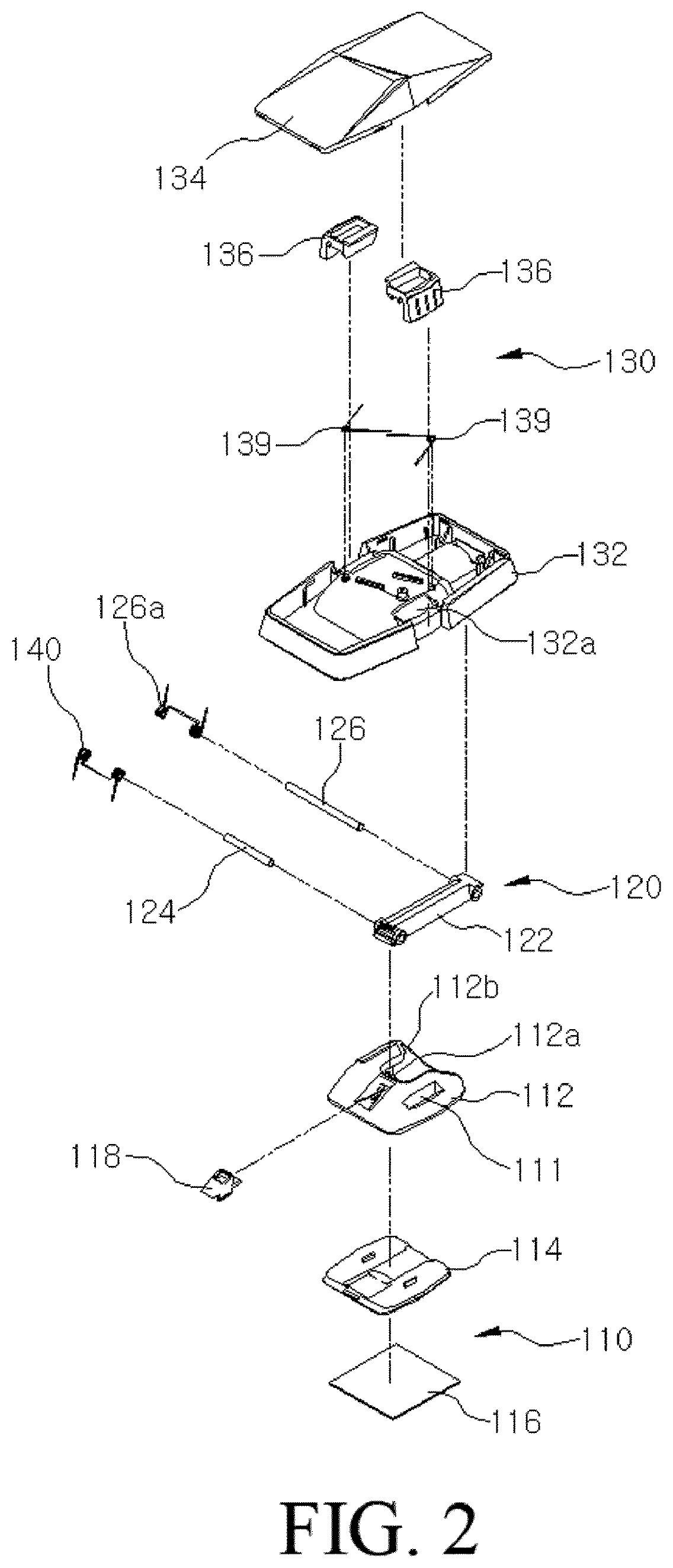
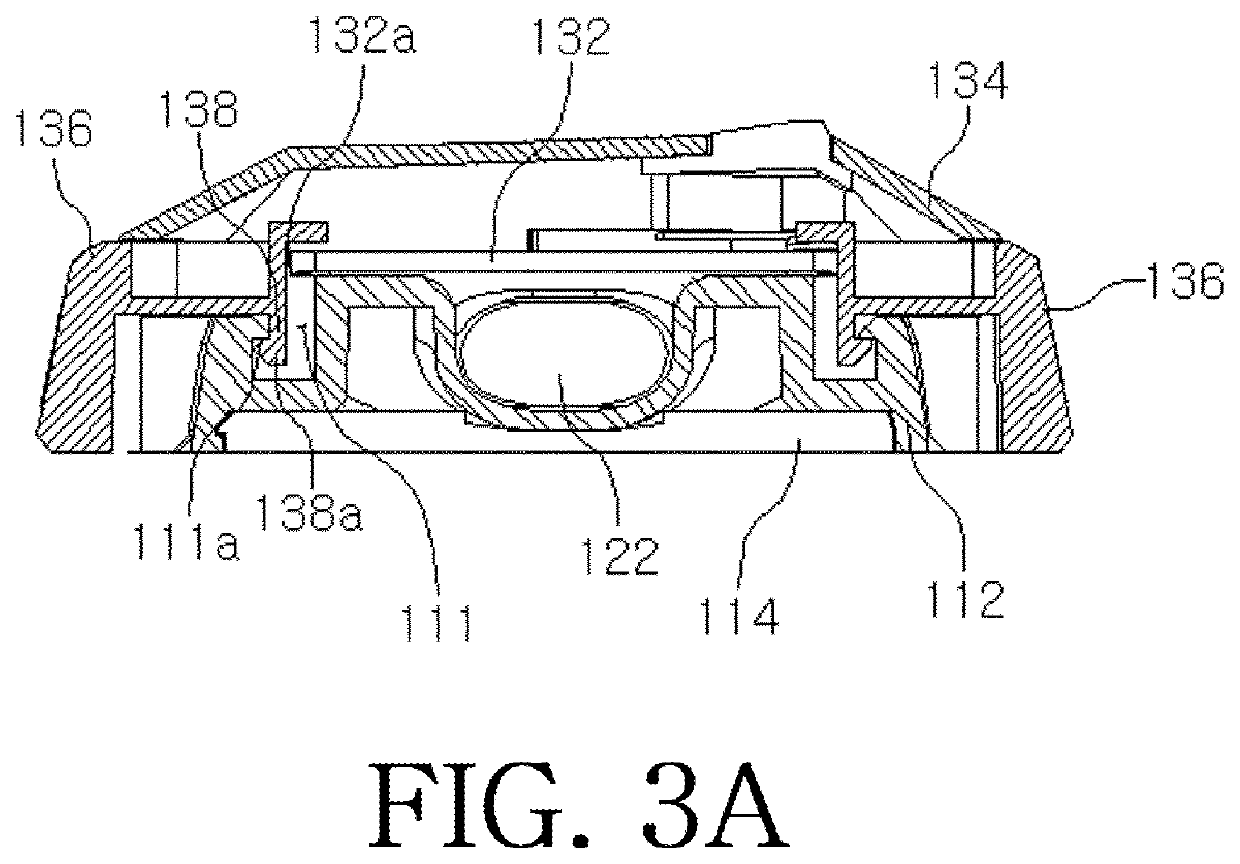
[0068]FIG. 1 is a perspective view illustrating a stand-holder for a portable terminal according to the first embodiment of the present disclosure, FIG. 2 is an exploded perspective view of the stand-holder of the first embodiment illustrated in FIG. 1, FIGS. 3A and 3B are cross-sectional views taken on line A-A′ of FIG. 1, FIGS. 4A and 4B are cross-sectional views taken on line B-B′ of FIG. 1, FIGS. 5A to 5C are views illustrating an operation relationship of the stand-holder of the first embodiment illustrated in FIG. 1, FIG. 6 is a view illustrating a support portion and an angle adjustment member of the stand-holder for the portable terminal according to the first embodiment, FIGS. 7A to 7C are views illustrating a state in which an angle of a coupling portion of the first embodiment illustrated in FIG. 1 is adjusted, and FIGS. 8 to 11 are views illustrating using states of the stand-holder for the portable terminal according to the first embodiment.

[0069]According to the first ...

second embodiment

[0141]Hereinafter, a stand-holder 200 for a portable terminal according to the second embodiment of the present disclosure will be described with reference to FIGS. 12 to 34.

[0142]FIG. 12 is a view illustrating a stand-holder 200 for a portable terminal when the stand-holder is used as a holder according to the second embodiment of the present disclosure, FIG. 13 is a perspective view of the stand-holder of the second embodiment, FIG. 14 is a view illustrating the holding portion and the case which are decoupled from each other according to the second embodiment, FIG. 15 is a view illustrating a state in which the coupling portion of the second embodiment is arbitrarily erected for convenience of explanation, FIG. 16 is a cross-sectional view of the stand-holder of the second embodiment illustrated in FIG. 15, FIG. 17 is a view illustrating the stand-holder of the second embodiment when the stand-holder is used as a stand, FIG. 18 is a view illustrating the stand-holder of the secon...


PUM


Abstract

According to an embodiment of the present disclosure, there is provided a stand-holder for a portable terminal, the stand-holder comprising: a support portion fixed to a rear surface of the portable terminal; a holding portion; and a coupling portion operatively coupled to each of the support portion and the holding portion. The coupling portion and the support portion are operatively coupled to each other, such that the coupling portion is rotated relative to the support portion. The coupling portion and the holding portion are operatively coupled to each other, such that the holding portion is rotated relative to the coupling portion.

Description

TECHNICAL FIELD[0001]The present disclosure relates to a stand-holder for a portable terminal, and more particularly, to a stand-holder for a portable terminal, which has a foldable structure in the form of “” and thus can have its size adjusted to an optimal size according to a size of a user's finger, which is in contact with both an upper portion and a lower portion of the user's finger, thereby providing a more comfortable and stable grip, and which has its shape transformed to the shape of “A” with respect to a portable terminal by an one-touch operation, and brings a front end of a holding portion into contact with a rear surface of the terminal for use, and also, stands the terminal on a floor surface at a predetermined angle in the landscape or portrait orientations, such that a user can view a video or surf the web more comfortably.BACKGROUND ART[0002]Recently, portable terminals such as smartphones or tablet PCs are widely used, and are essential portables to people of all...

Claims


Application Information

Patent Timeline
Patent Type & Authority Patents(United States)
IPC IPC(8): H05K5/02
CPCH05K5/0221H05K5/0234H05K5/0204H05K5/0226H04M1/04H04B1/3888A45F2200/0516A45C2200/15H04B1/3877F16M11/10F16M13/04F16M13/022F16M11/2021F16M2200/041F16M2200/044F16M11/38
Inventor LEE, KI BEOM
Owner LEE KI BEOM
Why Eureka
Try Eureka