knife pliers

A technology for pulling out pliers and pliers, which is applied in the field of equipment for taking out blades

Active Publication Date: 2016-08-24
WENZHOU ADEWO AUTOMATION EQUIP CO LTD
View PDF5 Cites 0 Cited by
  • Summary
  • Abstract
  • Description
  • Claims
  • Application Information

AI Technical Summary

Problems solved by technology

[0005] In the above technical solution, at the initial stage of the upward movement of the operating part, the cam block moves upward in the arc-shaped groove, prompting the upper end of the clip to open without vertical displacement. At this time, the lower end of the clip clamps the blade, and the operating part moves upward again. When the displacement occurs, the clip and the moving block will be driven upwards together. At this time, the moving block will collide with the guide part of the block. Through oblique guidance, it will overcome the elastic force of the compression spring and push the block to move to the side of the compression spring so that the block will no longer block. After moving the block, the clip can be moved upwards together, and the blade can be pulled out; so that the clamping blade and the upward pulling of the blade have a pause with a sharp increase in force, ensuring that the blade is clamped and then pulled out upwards, which can effectively avoid the occurrence of unclamped clips. When the blade is tightened, it moves upwards and the blade cannot be pulled out, thus improving the performance of the equipment

Method used


Image

  • knife pliers

Examples


Embodiment 1

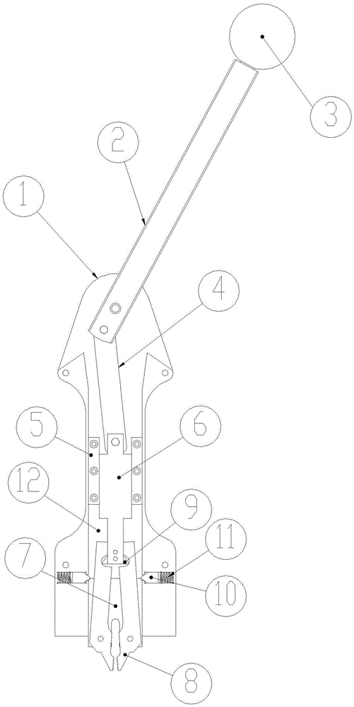
[0017] Such as figure 1 As shown, the knife-drawing pliers described in this embodiment includes a pliers body 1. The pliers body 1 can be combined with two panels with grooves in the middle. A vertical inner cavity 12 is formed in the middle of the pliers body 1. The inner cavity The lower end of 12 is provided with a moving block 7 that can be displaced up and down relative to the caliper body, and the moving block 7 is provided with two parts that form the clip 8 through the rotating shaft, and the two parts of the clip 8 rotate along the rotating shaft to realize the clamping and loosening of the clip 8; The inner sides of the upper ends of the two parts of the clip 8 are provided with arc-shaped grooves, and the upper end of the inner cavity 12 is provided with an operating piece that can displace up and down. The lower end of the operating piece is provided with a cam block 9, and the cam block 9 is located inside the arc-shaped groove; An accommodating groove is respect...


PUM


Abstract

The invention relates to the field of devices for taking out blades, in particular to a blade drawing tongs. The blade drawing tongs comprises a tong body, a vertical inner cavity is formed in the middle of the tong body, a moving block capable of moving up and down relative to the tong body is arranged at the lower end of the inner cavity, two parts forming a clamp are arranged on the moving block through a rotating shaft, and the two parts of the clamp rotate along the rotating shaft to achieve the clamping and releasing of the clamp. Arc grooves are formed in the inner sides of the upper ends of the two parts of the clamp, an operating part capable of moving up and down is arranged at the upper end of the inner cavity, cam blocks are arranged at the lower end of the operating part, and the cam blocks are located in the arc grooves. A containing groove is formed in inner wall of the part, located above the moving block, of the tong body. According to the blade drawing tongs, in the operation process, a handle is rotated, the cam blocks drive the clamp to conduct clamping, at the moment, springs exactly ejected by the check blocks are stressed, when the handle is rotated continuously, the elastic force of the springs needs to be broken through, larger force for drawing a blade is needed, and thus pause exists when the blade is drawn, in other words, the blade is drawn upwards after the blade is completely and tightly clamped.

Description

technical field [0001] The invention relates to the field of equipment for taking out blades, in particular to a knife-drawing pliers. Background technique [0002] In the original knife puller, align the clip mouth of the knife puller with the blade, operate the handle, control the clip to clamp the blade and move the clip upward, so that the blade is pulled out, clamping the blade and pulling it up are all done in one go without pause. It often happens that the blade is displaced upwards without being clamped, so that the blade cannot be pulled out smoothly. Contents of the invention [0003] The object of the present invention is to provide a kind of knife-drawing pliers that can move upwards after clamping the blade in order to solve the above-mentioned technical deficiencies. [0004] In order to achieve the above-mentioned purpose, the knife-drawing pliers designed by the present invention includes a pliers body, which is characterized in that: a vertical inner cham...

Claims


Application Information

Patent Timeline
Patent Type & Authority Patents(China)
IPC IPC(8): B25B27/02
CPCB25B27/02
Inventor 吴高峰杨树东吴起盛
Owner WENZHOU ADEWO AUTOMATION EQUIP CO LTD
Why Eureka
Try Eureka