Floor locking device for a wind turbine blade mould

a technology of locking device and wind turbine blade, which is applied in the field of locking, can solve the problems of damage to the mould, poor moulding tolerance, and inability to effectively level the mould, and achieve the effect of restricting or eliminating any distortion, and leveling the mould

Active Publication Date: 2020-10-13
GURIT TOOLING (TAICANG) CO LTD
View PDF19 Cites 0 Cited by
  • Summary
  • Abstract
  • Description
  • Claims
  • Application Information

AI Technical Summary

Benefits of technology

[0009]In light of the problems with potential poor levelness and potential distortion of the movement side of wind turbine blade moulds, in particular large wind turbine blade moulds as discussed above, the present invention aims effectively to solve these problems, and aims to provide a locking device which enables the movement side of a wind turbine blade mould to be clamped to the floor at a desired, accurately set, level so as to minimize, and preferably eliminate, potential movement and possible distortion of the wind turbine blade mould during the wind blade production process. The present invention accordingly provides a locking device for locking a movement side of a wind turbine blade mould to a floor at a desired level, the locking device comprising a first locking component for mounting to a floor surface and a second locking component adapted to be fitted to a movement side of a wind turbine blade mould to be locked by the locking device, wherein one of the first and second locking components comprises a clamp engaging member, and the other of the first and second locking components comprises an actuator and a clamp member coupled to the actuator, the clamp member being movable by operation of the actuator between a retracted position and an extended position, the clamp member including a clamp surface which in the one of the retracted and extended positions is arranged to apply a clamping force on the clamp engaging member.
[0035]The locking device of the preferred embodiments of this invention can function to lock the movement side of the mould onto the floor by providing an adjustable floor locking device. The floor locking device can adjust the levelness and restrict the distortion of the movement side. For instance, when installing the shear web on the mould at the movement side, the locking device of the preferred embodiment of this invention can helps to reduce installation deviation between the blade at movement side and the molded surface of the shear web, and can thus improve the blade quality.
[0036]The locking device of the preferred embodiment of this invention can function to adjust the levelness at the movement side of an adjustable wind turbine blade mould.
[0040]When the mould is opened and the movement side turned onto the floor, the floor locking device can be used to firmly lock the frame, typically of steel, at the movement side, and can adjust the levelness of the mould and restrict or eliminate any distortion at the movement side of the mould.

Problems solved by technology

When the movement side of the mould is turned onto the floor in a traditional way, there is no effective levelness-adjusting device and levelness-fixing at the movement side.
However, if the floor is uneven or of an incorrect height, all or parts of the movement side can be supported at varying or incorrect levels.
This can distort the movement side of the mould, potentially leading to damage of the mould and / or poor moulding tolerances.
Traditionally, there has been no effective levelness-adjusting device and / or distortion restricting device provided at the movement side of the mould.

Method used


Image

  • Floor locking device for a wind turbine blade mould
  • Floor locking device for a wind turbine blade mould
  • Floor locking device for a wind turbine blade mould

Examples


first embodiment

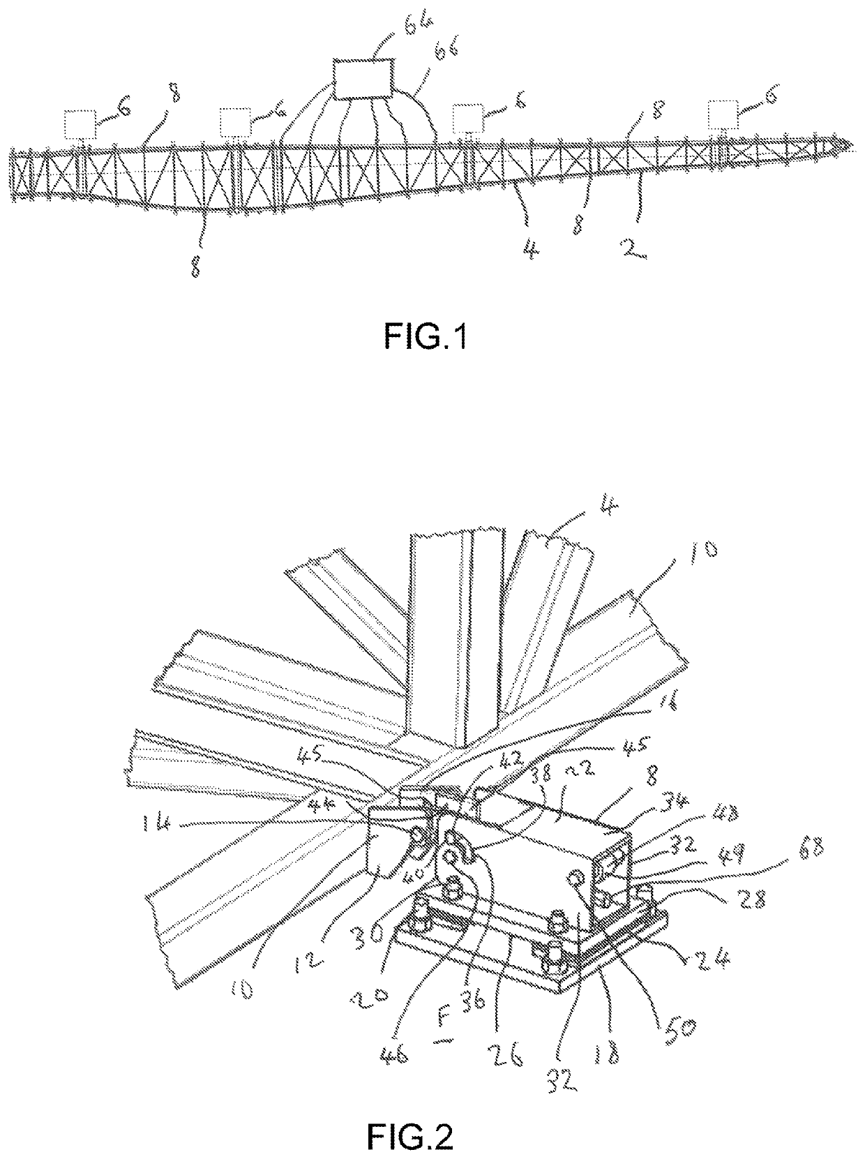
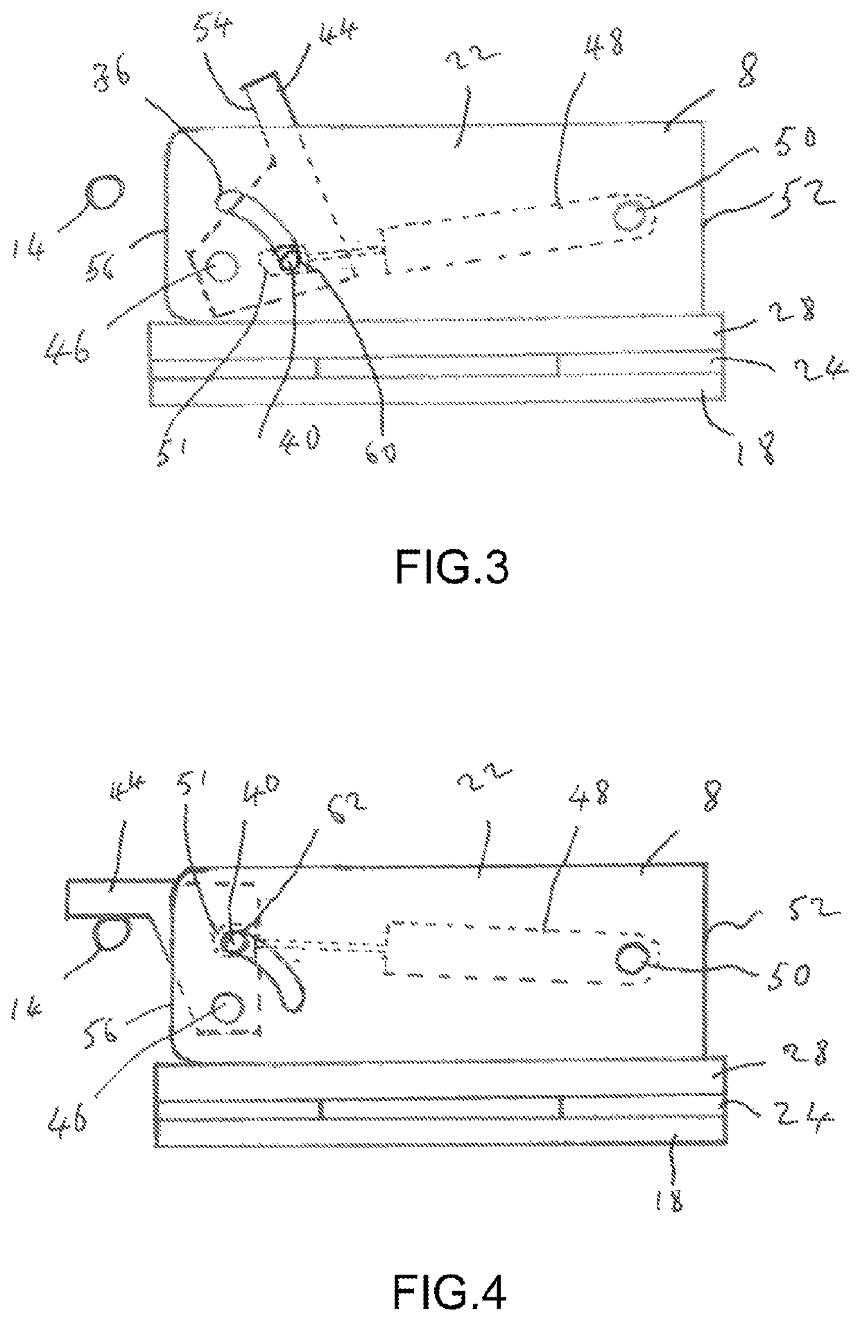
[0051]Referring also to FIGS. 2 to 4, which illustrate the present invention, the locking device 8 comprises a first locking component 100 for mounting to a floor surface F and a second locking component 102 adapted to be fitted to the movement side 4 of the wind turbine blade mould 2 to be locked by the locking device 8. The location of each locking device 8 is selected so that the locking device 8 can securely clamp to a clamp engaging member 12 fixed to the steel framework 10 of the movement side 4. In this embodiment, locking devices 8 are provided along both longitudinal edges of the movement side 4. Typically, the locking devices are spaced from each other by a distance significantly smaller than the separation distance of the rotary mechanisms 6. The same spacing distance is typically used along the length of the movement side 4. For example, the locking devices may be spaced from each other by a distance of from 1 to 2 metres, although other distance may be employed, for exa...

second embodiment

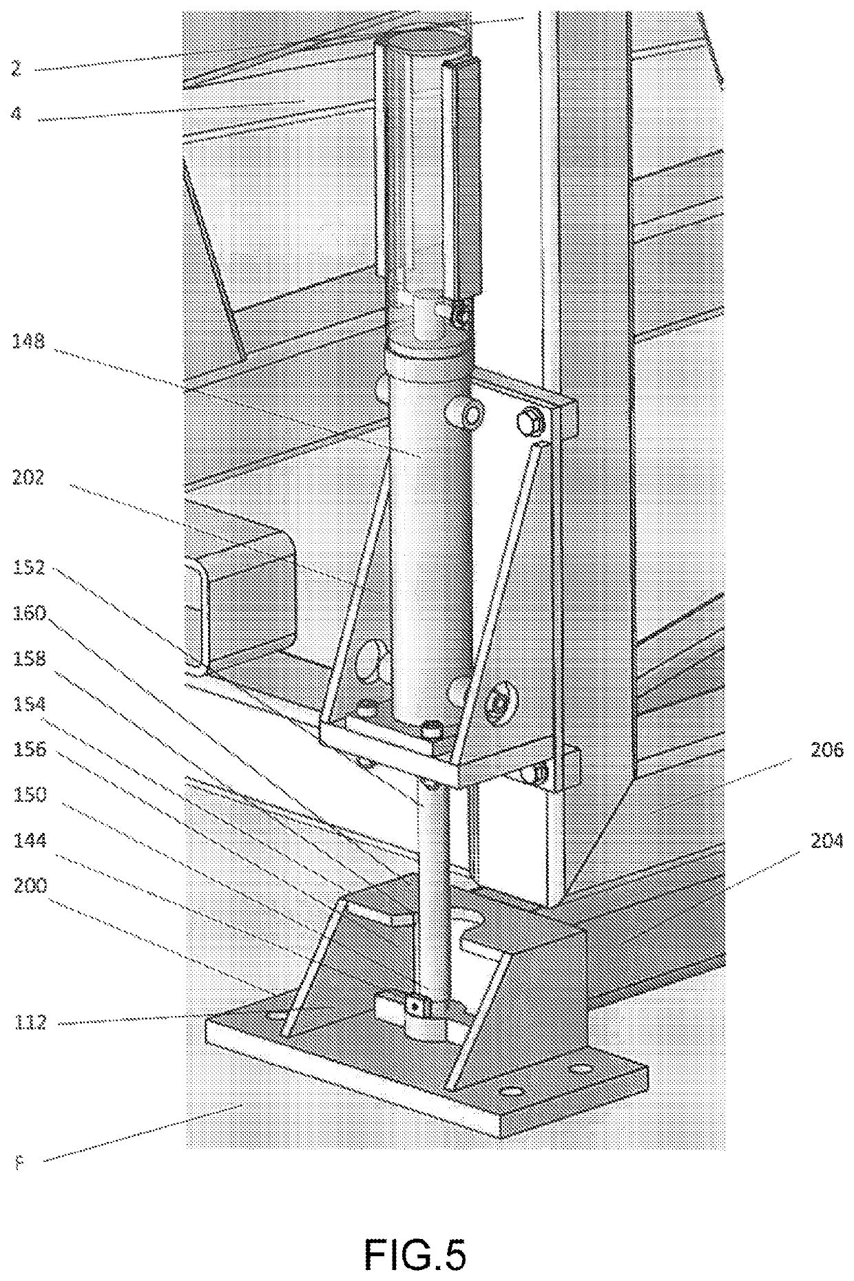
[0069]Referring also to FIGS. 5 and 6, which illustrate the present invention, the actuator 148 is substantially vertically oriented and the retracted and extended positions of the clamp member 144 are substantially vertically separated in the extended and retracted position. In this embodiment, the first locking component 200, fitted to the floor F, comprises the clamp engaging member 112 and the second locking component 202, fitted to the mould 2, comprises the actuator 148 which is fitted to the movement side 4 of the wind turbine blade mould 2 and the clamp member 144. An elongate support base 204 extends away from, and is preferably connected to, the first locking component 200, for example a rear part of the clamp engaging member 112, and is set at a level, e.g. horizontal, orientation. The elongate support base 204 is arranged to support an elongate frame member 206 of the movement side 4 and to keep the movement side 4 level when the movement side 4 is in an open configurati...


PUM

PropertyMeasurementUnit
lengthaaaaaaaaaa
lengthaaaaaaaaaa
lengthaaaaaaaaaa

Abstract

Locking device for locking a movement side of a wind turbine blade mould to a floor at a desired level, the locking device having a first locking component for mounting to a floor surface and a second locking component adapted to be fitted to a movement side of a wind turbine blade mould to be locked by the locking device, wherein one of the first and second locking components includes a clamp engaging member, and the other of the first and second locking components includes an actuator and a clamp member coupled to the actuator, the clamp member being movable by operation of the actuator between a retracted position and an extended position, the clamp member including a clamp surface which in one of the retracted and extended positions is arranged to apply a clamping force on the clamp engaging member.

Description

FIELD OF THE INVENTION[0001]The present invention relates to a locking device for locking a movement side of a wind turbine blade mould to a floor at a desired level. The present invention particularly relates to such a locking device which enables the movement side of a wind turbine blade mould to be clamped to the floor at a desired level so as to minimize movement and possible distortion of the wind turbine blade mould during the wind blade production process.BACKGROUND OF THE INVENTION[0002]With the development of science and technology, wind power as a safe and green renewable energy has developed rapidly. In recent years, the production technology of wind turbine blades has been continuously developed and improved. Current wind turbine blades typically have a length of more than 50 metres and are moulded out of fibre reinforced resin composite material.[0003]Accordingly, exceedingly large moulds are required which have a mould surface corresponding to the dimensions of the win...

Claims


Application Information

Patent Timeline
Patent Type & Authority Patents(United States)
IPC IPC(8): B29C33/30B29C33/26B29C33/20B29L31/08
CPCB29C33/20B29C33/30B29C33/26Y02P70/50B29L2031/085
Inventor GAO, QIANG
Owner GURIT TOOLING (TAICANG) CO LTD
Why Eureka
Try Eureka