
Vein ablation device

a vein ablation and vein technology, applied in the field of vein ablation devices, can solve the problems of non-invasive devices, high risk of surgical complications, and the risk of damage to nearby nerves of cather based devices, and achieve the effects of reducing the risk of surgical complications, and reducing the safety of patients

Active Publication Date: 2020-10-13
V V T MED
View PDF31 Cites 0 Cited by
  • Summary
  • Abstract
  • Description
  • Claims
  • Application Information

AI Technical Summary

Benefits of technology

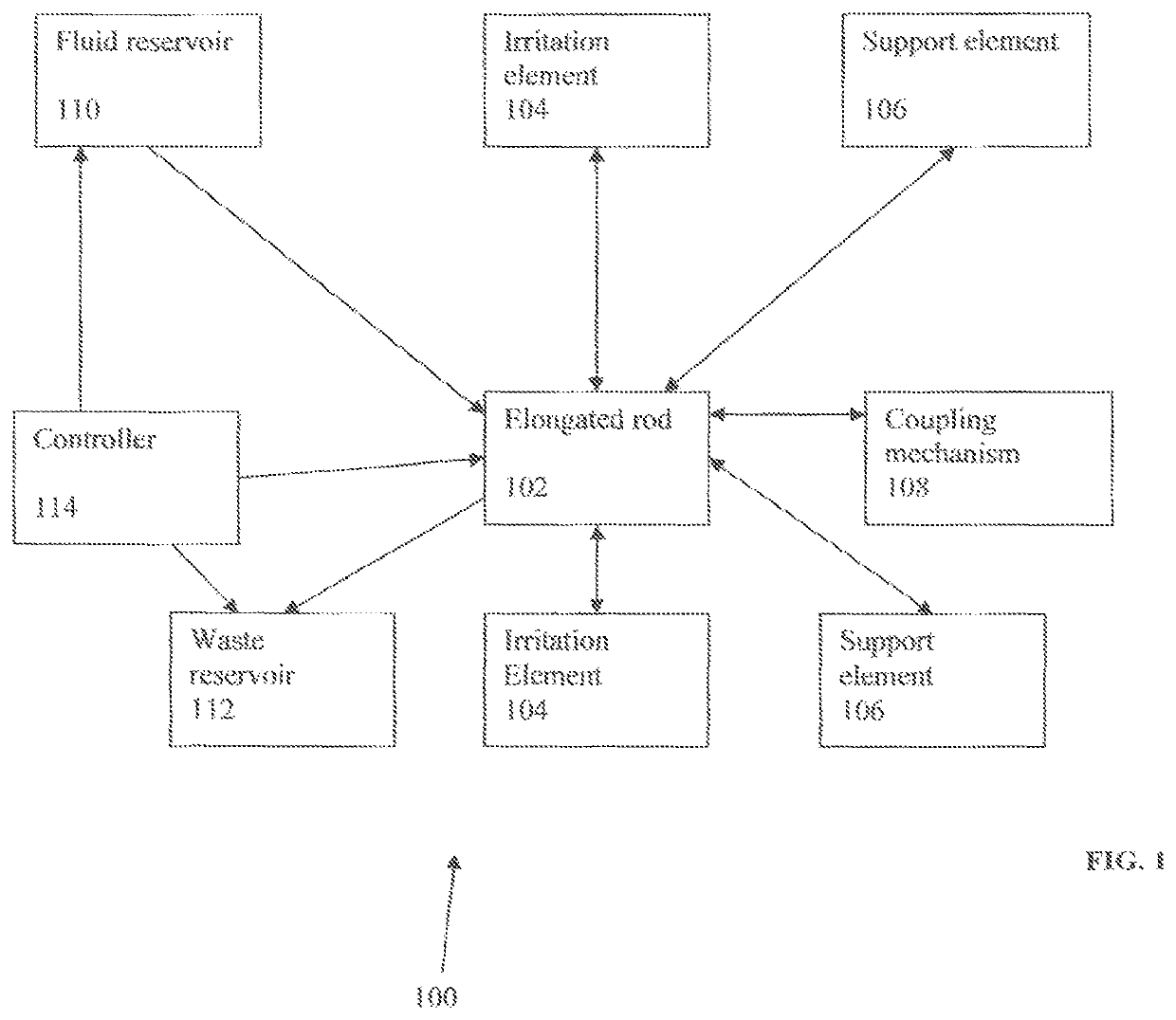
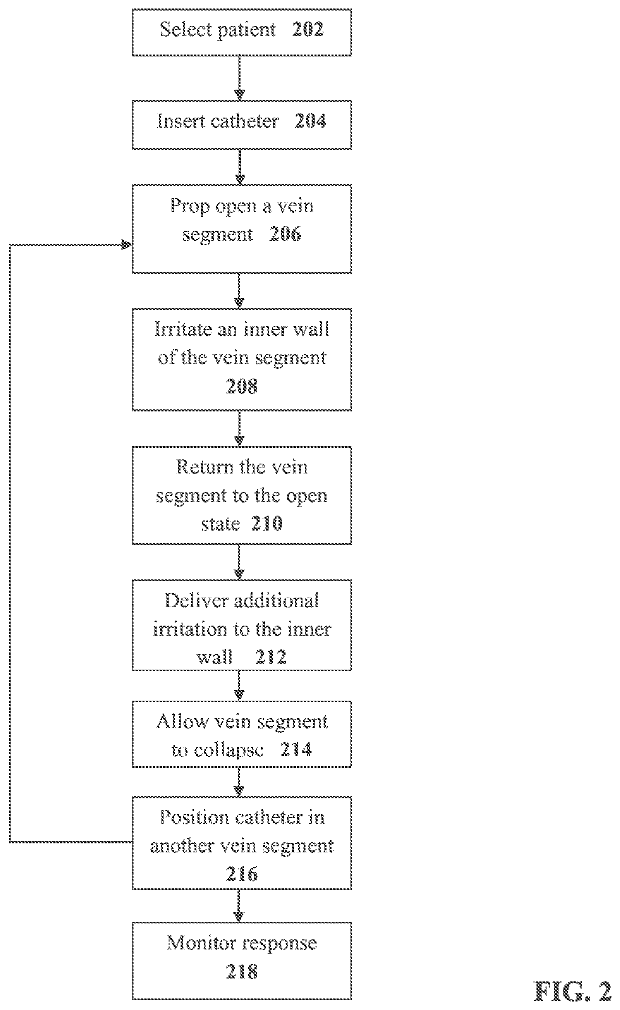
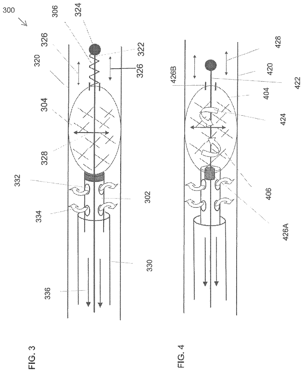
The present invention relates to a device and method for mechanically irritating the inner wall of a vein to trigger spasm and ablate the vein. The device includes an elongated rod with an irritation element and a support element that applies a mechanical force to return the vein segment to its original state. The support element can be a balloon or a resilient element that applies the force. The irritation element can be a tubular mesh or a plurality of elevated parallel tracks. The device can also include a fluid insertion channel for releasing a medical substance and a fluid removal channel for removing fluid and debris. The method involves propping open the vein segment, mechanically irritating the inner wall, applying a mechanical force to return the vein segment to its original state, and optionally delivering a sclerosing agent to the inner wall. The device and method can be used for vein ablation.

Problems solved by technology

The non-invasive devices, such as compression stockings generally have limited efficacy, especially for more severe cases.
The surgical techniques may produce better results, but with the risk of surgical complications.
Cather based devices that emit energy (e.g., heat, radiofrequency, laser) run the risk of damage to nearby nerves and may not be very effective due to recanalization.

Method used


Image

  • Vein ablation device
  • Vein ablation device
  • Vein ablation device

Examples


Embodiment Construction

[0056]As used herein, the term “proximal” means closer to the operator of the catheter.

[0057]As used herein, the term “distal” means further away from the operator of the catheter.

[0058]As used herein, the phrase “inner wall” means the inner tissue layer of the vein wall, the intima or endothelial cell layer.

[0059]An aspect of some embodiments of the present invention relates to endovascular catheters and / or methods of use thereof where a catheter comprises an irritation element at a distal end thereof to irritate an inner wall of a vein segment, and a support element at a distal end portion thereof to apply a mechanical force from the distal end portion to iteratively return the irritation element to the expanded irritation state in response to dynamic feedback of vein walls pressing against the irritation element to force the irritation element into the non-irritation state. Optionally, the force applied by the support element returns the irritation element to the irritation state...


PUM


Abstract

An endovascular catheter for vein ablation comprising: an elongated rod sized for insertion into a vein; at least one irritation element coupled to the distal end portion of the rod, the at least one irritation element having an expanded irritation state for contacting an inner wall segment of the vein to irritate the vein segment to trigger spasm of the vein segment and a non-irritation state, the at least one irritation element arranged for iterative changes between the irritation state and the non-irritation state; and at least one support element coupled to the distal end portion of the rod, the support element arranged to apply a mechanical force from the distal end portion to iteratively return the irritation element to the expanded irritation state in response to dynamic feedback of vein walls pressing against the irritation element to force the irritation element into the non-irritation state.

Description

RELATED APPLICATIONS[0001]The present application is a National Phase of PCT Patent Application No. PCT / IL2014 / 050863 having International filing date of Oct. 1, 2014, which claims the benefit of priority under 35 USC § 119(e) of U.S. Provisional Patent Application No. 61 / 890,269 filed on Oct. 13, 2013. The contents of the above applications are all incorporated by reference as if fully set forth herein in their entirety. PCT Patent Application No. PCT / IL2014 / 050863 is related to co-filed, co-pending and co-assigned PCT Patent Application Nos. PCT / IL2014 / 050864 and PCT / IL2014 / 050862, both by the same inventor, Zeev Brandeis. PCT Patent Application No. PCT / IL2014 / 1050864 relates to devices and methods for synchronized injection and aspiration. PCT Patent Application No. PCT / IL2014 / 050862 relates to devices and methods for foam formation. The contents of the above applications are all incorporated by reference as if fully set forth herein in their entirety.FIELD AND BACKGROUND OF THE ...

Claims


Application Information

Patent Timeline
Patent Type & Authority Patents(United States)
IPC IPC(8): A61B17/12A61B17/00A61B17/3207A61M37/00A61B17/32
CPCA61B17/12186A61B17/00008A61B17/12136A61B17/320725A61B17/320758A61M37/00A61B2017/00893A61B2017/320004A61B2017/320064A61B2017/320733
Inventor BRANDEIS, ZEEV
Owner V V T MED
Learn More