Ratchet chain binder

a chain binder and ratchet technology, applied in the field of ratchet chain binder, can solve the problems of laborious operation and large volume of the entire seat, and achieve the effect of saving labor

Active Publication Date: 2020-08-25
ZHEJIANG TOPSUN LOGISTIC CONTROL CO LTD
View PDF27 Cites 4 Cited by
  • Summary
  • Abstract
  • Description
  • Claims
  • Application Information

AI Technical Summary

Benefits of technology

[0007]One object of one embodiment of the present invention is to solve the above problems in the prior art, and to provide a ratchet chain binder. The technical problem to be solved by the present invention is how to make operating the ratchet chain binder more labor-saving.

Problems solved by technology

In addition, for one embodiment of the ratchet chain binder, it is necessary to ensure that the handle has a sufficient swing range to avoid small swing range of the handle requiring an increased number of swings, resulting in laborious operation.
Such disposition leads to a large spacing between the two drive bevel gears, and at the same time, a diameter of the transmission bevel gear is required to be made larger, resulting in a larger volume of the entire seat.

Method used


Image

  • Ratchet chain binder
  • Ratchet chain binder
  • Ratchet chain binder

Examples


embodiment 1

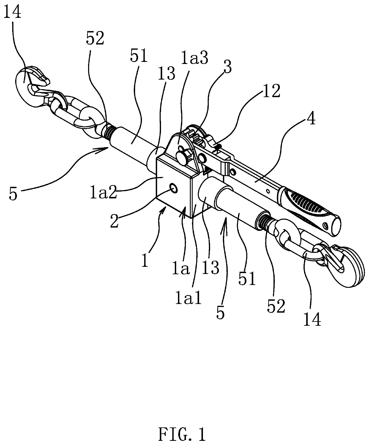
[0034]As shown in FIG. 1, one embodiment of a ratchet chain binder comprises a seat 1, a ratchet 3, a handle 4 capable of driving the ratchet 3 to rotate, and two screw tightening components 5 rotatably connected to the seat 1 in a coaxial manner. Each of the two screw tightening components 5 comprises a sleeve 51 rotatably disposed on the seat 1, a second end 512 of the sleeve 51 is inserted with a screw 52 and the screw 52 is threaded into the sleeve 51, and a free end of the screw is provided with a hook 14.

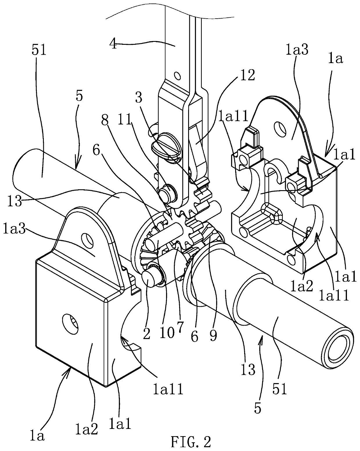
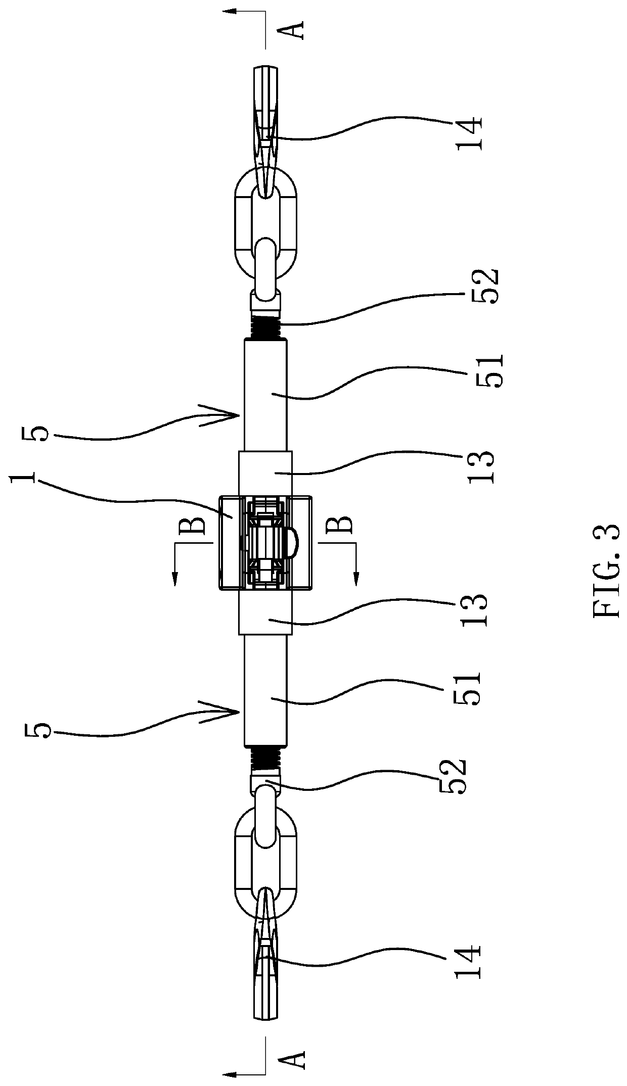
[0035]As shown in FIG. 2, FIG. 3 and FIG. 4, one embodiment of the handle 4 drives the ratchet 3 to rotate through a pawl 12. A rotating shaft 2 is rotatably disposed in the seat 1, the rotating shaft 2 is perpendicular to the sleeves 51, end faces of opposing first ends 511 of the two sleeves 51 are respectively provided with a drive bevel gear 6, and the drive bevel gear 6 is integrally formed with the sleeve 51. The rotating shaft 2 is provided with a transmission gear 7 an...

embodiment 2

[0040]The structures and principles of this embodiment are basically the same as those of the first embodiment, and the differences are that the diameter of the intermediate gear 8 is greater than the diameter of the transmission gear 7. Spaces in which the intermediate gear 8 and the ratchet 3 being positioned are respectively larger than an installing space of the transmission gear 7. Therefore, the diameter of the ratchet 3 is larger than the diameter of the intermediate gear 8, and the diameter of the intermediate gear 8 is larger than the diameter of the transmission gear 7, thus forming a two-stage downshift and achieving an object of labor-saving.

[0041]The specific embodiments described herein are merely illustrative of the spirit of the present invention. Technical personnel skilled in the art to which the present invention pertains can make various modifications or additions to the specific embodiments described or replace them in a similar manner, without departing from th...


PUM


Abstract

The ratchet chain binder comprises a seat, a rotating shaft, a ratchet, a handle capable of driving the ratchet to rotate, and two screw tightening components rotatably connected to the seat in a coaxial manner. Two drive bevel gears are disposed respectively on opposing ends of the two screw tightening components. The rotating shaft is provided with a transmission gear and a transmission bevel gear simultaneously engaging the two drive bevel gears, the rotating shaft is capable of driving the two screw tightening components to rotate and changing an overall length of the two screw tightening components. The transmission gear is disposed between the two screw tightening components, an intermediate gear is rotationally connected to the seat, and the ratchet is located above the intermediate gear and engages with the intermediate gear.

Description

RELATED APPLICATIONS[0001]This application claims priority to Chinese Patent Application No. CN201811417240.6, filed Nov. 26, 2018.[0002]The above applications and all patents, patent applications, articles, books, specifications, other publications, documents, and things referenced herein are hereby incorporated herein in their entirety for all purposes. To the extent of any inconsistency or conflict in the definition or use of a term between any of the incorporated publications, documents, or things and the text of the present document, the definition or use of the term in the present document shall prevail.BACKGROUND OF THE INVENTIONField of Invention[0003]The present invention belongs to the technical field of binding tools and relates to a ratchet chain binder.Related Art[0004]During transportation of goods, the goods usually need to be bundled. There are various types of ratchet chain binders, and the screw type ratchet chain binder is a tool that changes a distance between th...

Claims


Application Information

Patent Timeline
Patent Type & Authority Patents(United States)
IPC IPC(8): B60P7/08F16G11/12F16H25/20
CPCF16H25/20B60P7/083F16G11/12F16H2025/2093F16H2025/2059B60P7/06F16H57/023
Inventor RUAN, BUQINZHU, ZHENGZHONG
Owner ZHEJIANG TOPSUN LOGISTIC CONTROL CO LTD
Why Eureka
Try Eureka