Ring clamp

a technology of ring clamping and clamping rod, which is applied in the field can solve the problems of inconvenient use and laborious closing action of ring clamping rod, and achieve the effect of convenient use and more labor-saving

Active Publication Date: 2016-04-12
WORLD WIDE STATIONARY MFG CO LTD
View PDF10 Cites 0 Cited by
  • Summary
  • Abstract
  • Description
  • Claims
  • Application Information

AI Technical Summary

Benefits of technology

[0008]The present invention relates to a novel ring clamp, which comprises a housing, an articulated plate, at least two rings, a handle and a slide plate, wherein the articulated plate consists of a first articulated plate and a second articulated plate which are articulated with each other; an articulated axis is disposed in the middle of the articulated plate; the first articulated plate and the second articulated plate are pivoted relative to the articulated axis; both sides of the articulated plate are connected with the housing; each ring consists of a first ring member and a second ring member; the first ring member and / or the second ring member are / is connected with the articulated plate; when the articulated plate is pivoted, the first ring member and the second ring member are opened or closed along with the pivoting of the articulated plate; after the articulated plate is pivoted towards the outside of the housing and crosses a coplanar position, the first ring member and the second ring member are closed to form a ring; the handle is connected with the housing and can drive the pivoting of the articulated plate; the slide plate is arranged between the housing and the articulated plate, is connected with the handle, and can move relative to the housing; a locking position is disposed on a movement locus; when the ring clamp is in the closed state, the slide plate moves to the locking position and abuts against the articulated plate so as to lock the articulated plate; the slide plate can be departed from the locking position along with the pulling of the handle, so that the articulated plate can be driven to rotate by the handle; the handle or the slide plate is provided with an idle stroke section, so that the slide plate does not slide towards the locking position along with the closing of the handle in the initial phase of the closing of the ring clamp; the ring clamp is provided with a magnetic structure; and after the articulated plate crosses the coplanar position along with the closing of the handle, the slide plate is adsorbed to the locking position by the magnetic force generated by the magnetic structure, so that the articulated plate can be locked.
[0017]The ring clamp provided by the present invention has the advantages that: as the handle or the slide plate is provided with the idle stroke section in the present invention, the slide plate does not slide to the locking position along with the closing of the handle in the initial phase of the closing of the ring clamp, and the articulated plate can cross the coplanar position along with the closing of the handle so as to close the clamp; as the ring clamp is provided with the magnetic structure, after the articulated plate crosses the coplanar position along with the closing of the handle so as to close the clamp, the slide plate is adsorbed to the locking position by the magnetic force, and hence the articulated plate is locked; and therefore, compared with the prior art, the ring clamp provided by the present invention does not need to overcome the tension generated by the deformation of the intermediate connector so as to close the ring clamp, and hence the closing action is more laborsaving and the ring clamp is more convenient to use.

Problems solved by technology

The above patent utilizes the tension generated by the deformation of the intermediate connector to push the locking members to the locking positions, and has the defects that: as each closing action of the ring clamp structure needs to overcome the tension generated by the deformation of the intermediate connector so as to close a ring clamp, the closing action is laborious and the ring clamp is inconvenient to use.

Method used


Image

  • Ring clamp
  • Ring clamp
  • Ring clamp

Examples


embodiment 1

[0031]

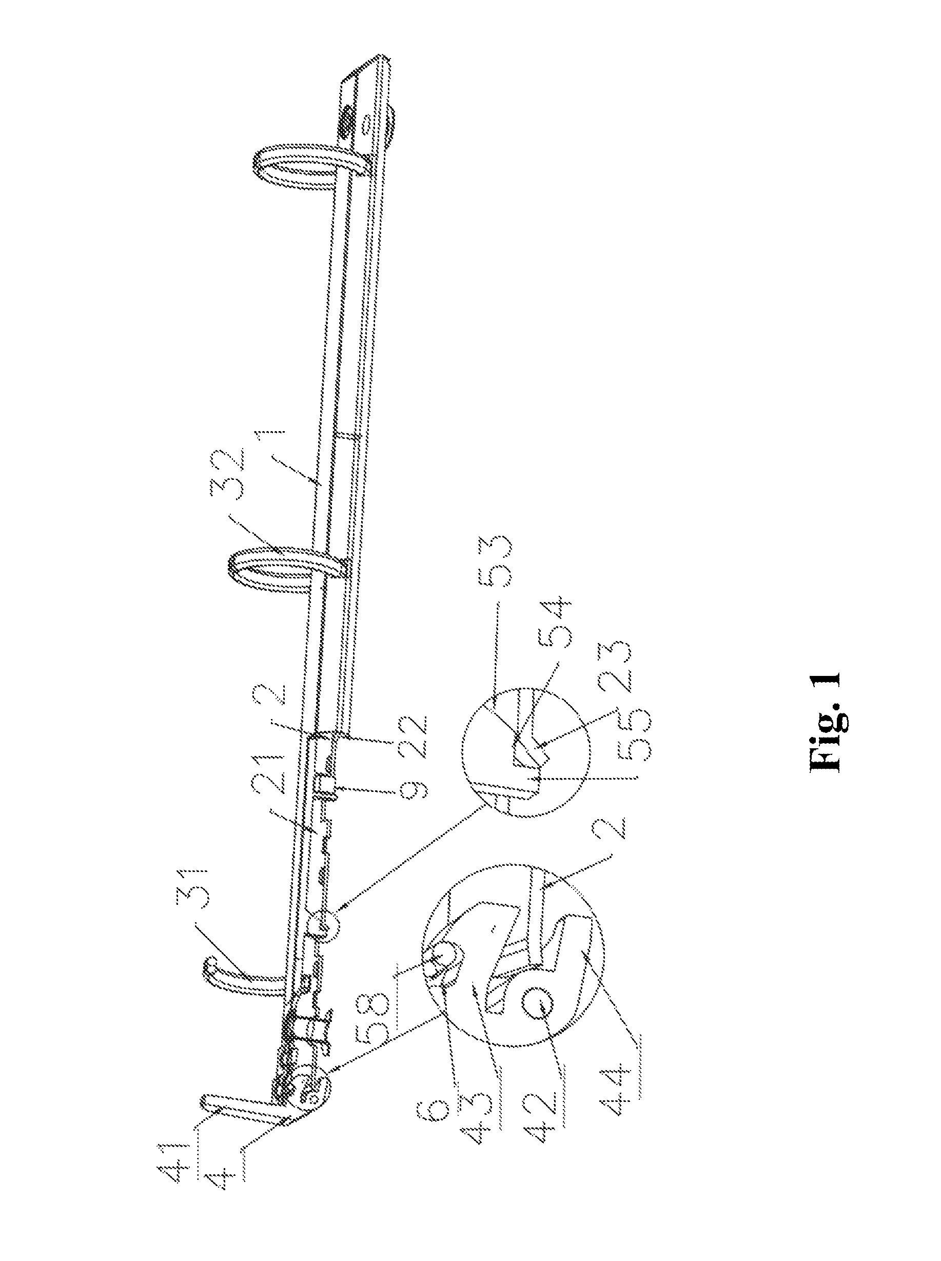
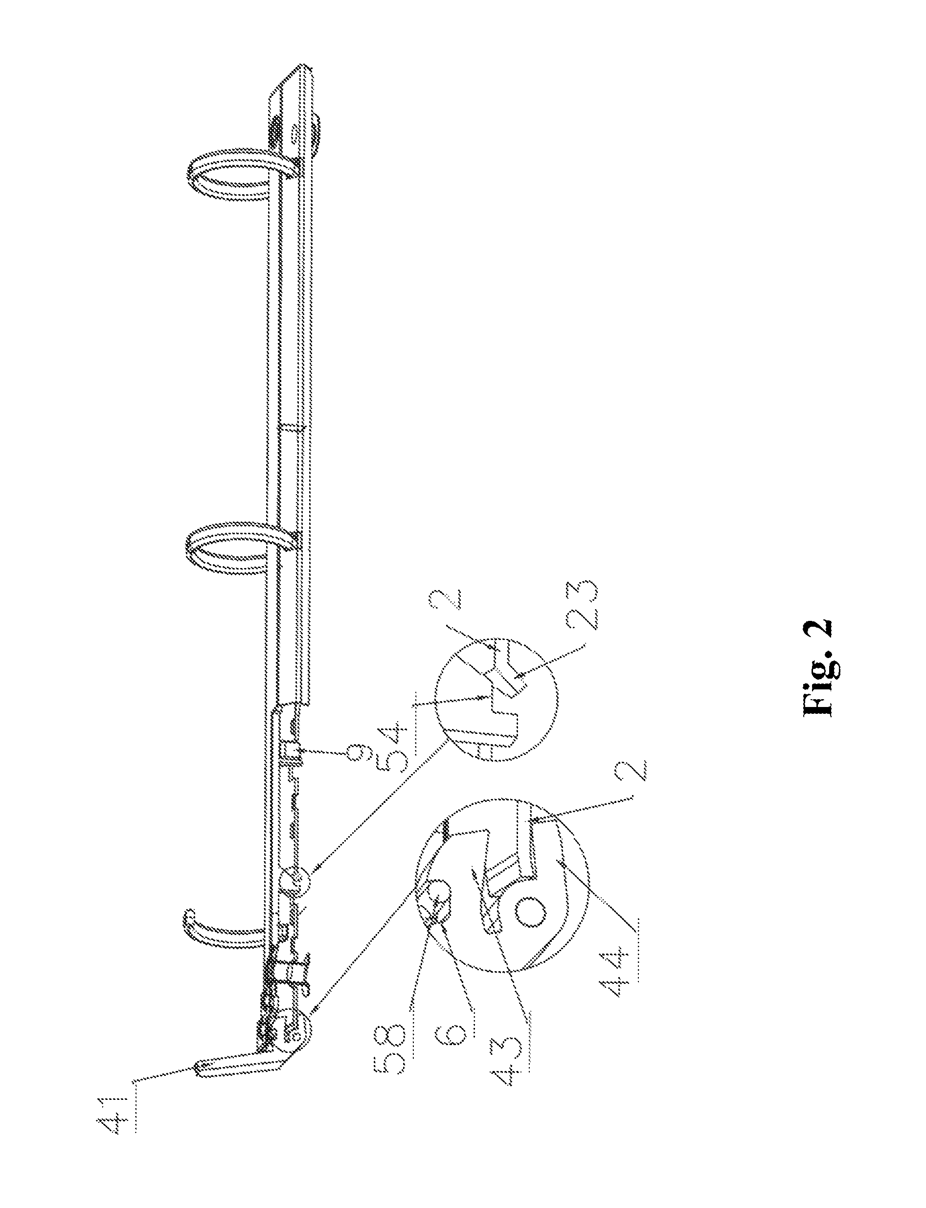
[0032]As illustrated in FIGS. 1 to 7, the clamp ring provided by the present invention comprises a housing 1 and an articulated plate 2, wherein the articulated plate 2 consists of a first articulated plate 21 and a second articulated plate 22 which are articulated with each other; an articulated axis is disposed in the middle of the articulated plate 2; both sides of the housing 1 are bent so as to clamp the articulated plate 2 at the bottom; and both sides of the articulated plate 2 are connected with the housing 1. Moreover, the width of the housing 1 is varied along with the pivoting of the articulated plate 2. When the articulated plate 2 is at a coplanar position (namely when the first articulated plate 21 and the second articulated plate 22 are in the same plane), the housing 1 is stretched to the maximum width by the articulated plate 2. When the articulated plate 2 is pivoted (namely when the first articulated plate 21 and the second articulated plate 22 are not at th...

embodiment 2

[0046]

[0047]As illustrated in FIG. 8, the differences of the embodiment with the embodiment 1 are as follows: the slide plate 5 further includes a tension rod 57; the idle stroke section 6 is disposed on the connecting rod 51 of the slide plate 5; and one end of the tension rod 57 is tightly connected with the handle 4 and the other end of the tension rod 57 is connected with the idle stroke section 6 of the connecting rod 51. The idle stroke section 6 is, more specifically, a through hole formed on the connecting rod 51. As the idle stroke section 6 is disposed on the slide plate 5, the manufacturing precision can be more easily controlled compared with the case that the idle stroke section 6 is disposed on the handle 4. Other structures of the embodiment 2 are the same with those of the embodiment 1 and will not be further described herein.

embodiment 3

[0048]

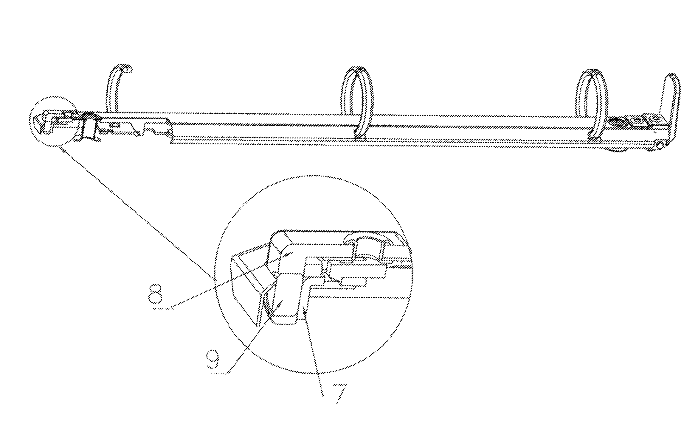
[0049]As illustrated in FIG. 9, the differences of the embodiment with the embodiment 1 are as follows: a first adsorbing member, i.e. a magnetic member 9, is disposed on the end portion of the housing 1 away from the handle 4; and a second adsorbing member, i.e. an angle iron 7, made of ferrous metals, is fixed on the end portion of the slide plate 5 facing the magnet. More specifically, in the embodiment, the ring clamp further comprises a rubber magnet support 8 and a second fixing member configured to fix the rubber magnet support 8 on the housing 1, wherein the rubber magnet support 8 is provided with a fixing hole; the magnetic member 9 is fixed in the fixing hole; and the second fixing member may be a rivet. Compared with the case that the magnetic member 9 is fixed on the slide plate 5, the mounting space of the embodiment is larger. Other structures of the embodiment 3 are the same with those of the embodiment 1 and will not be further described herein.


PUM


Abstract

A novel ring clamp, which comprises a housing, an articulated plate, rings, a handle and a slide plate, wherein the handle or the slide plate is provided with an idle stroke section, so that the slide plate does not slide towards a locking position along with the closing of the handle in the initial phase of the closing of the ring clamp; the articulated plate can cross a coplanar position along with the closing of the handle so as to close the clamp; the ring clamp is provided with a magnetic structure; and after the articulated plate crosses the coplanar position along with the closing of the handle so as to close the clamp, the slide plate is adsorbed to the locking position by the magnetic force, so that the articulated plate can be locked.

Description

FIELD OF THE INVENTION[0001]The present invention relates to the field of fixtures for filing appliances, in particular to a novel ring clamp.BACKGROUND OF THE INVENTION[0002]Ring clamps are usually fixed on filing appliances or notebooks. When the ring clamp is in the opened state, perforated loose-leaf paper can be added or removed. When the ring clamp is in the closed state, the loose-leaf paper is sleeved into rings of the ring clamp and can turn over along the rings.[0003]The Chinese patent titled “ring clamp structure” (the patent application number: 200710129155.5) discloses a ring structure for retaining loose-leaf paper, which comprises a housing and articulated plates which are supported by the housing to perform pivoting movement relative to the housing, wherein ring members are mounted on the articulated plates and can move between closed positions and opened positions; an actuator is mounted on the housing and configured to move relative to the housing, so that the pivo...

Claims


Application Information

Patent Timeline
Patent Type & Authority Patents(United States)
IPC IPC(8): B42F13/22B42F13/26
CPCB42F13/22B42F13/26
Inventor LIN, CHUNHAI
Owner WORLD WIDE STATIONARY MFG CO LTD
Why Eureka
Try Eureka