Optical image measurement apparatus and optical image measurement method
a technology of optical image and measurement apparatus, which is applied in the field of optical image measurement apparatus and optical image measurement method, can solve the problems that the typical oct that measures the reflectance distribution cannot visualize birefringence, and achieve the effects of suppressing and increasing the size and cost of the apparatus
- Summary
- Abstract
- Description
- Claims
- Application Information
AI Technical Summary
Benefits of technology
Problems solved by technology
Method used
Image
Examples
embodiment 1
eory of Optical System
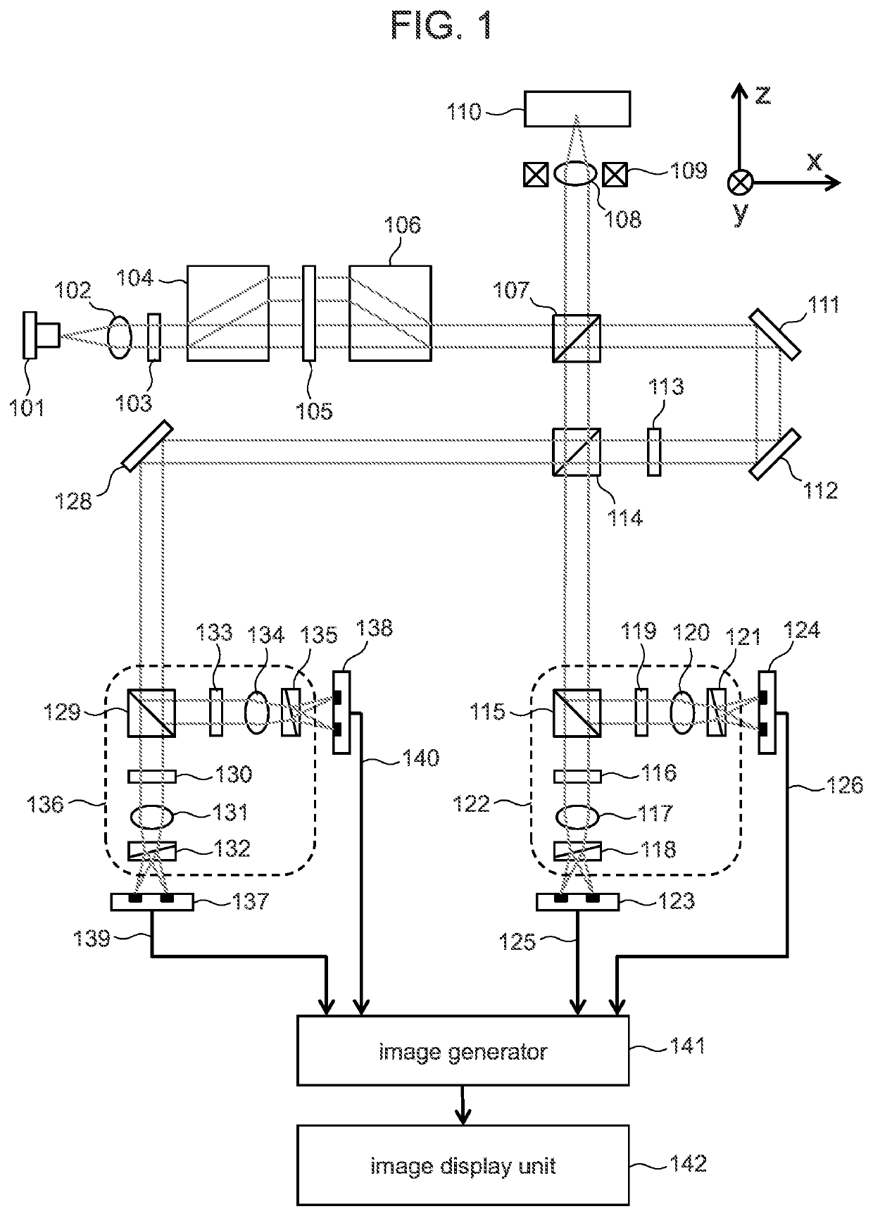
[0047]Hereinafter, the operation theory and the effect of the optical image measurement apparatus according to the embodiment 1 will be described in details using equations. The Jones matrix of the sample and the Jones vectors of the first and the second measurement light are described by Equations 1-3 below.
[0048][Equation1]R=(rpprpsrsprss)(1)[Equation2]Eprob,1=2(Eprob0)(2)[Equation3]Eprob,2=2(0Eprob)(3)
[0049]The Jones vectors of the first and the second signal light after passing through the polarization beam splitter 114 are described by Equations 4 and 5 below.
[0050][Equation4]Esig,1=(rpprsp)Eprob(4)[Equation5]Esig,2=(rpsrss)Eprob(5)
[0051]If the Jones vectors of the first and the second reference light are described by Equations 6 and 7 below, the Jones vectors of the first to fourth multiplexed light are given by Equations 8-11 below.
[0052][Equation6]Eref,1=(11)Eref(6)[Equation7]Eref,2=(1-1)Eref(7)[Equation8]E1=(rppEprobEref)(8)[...
embodiment 1 summary
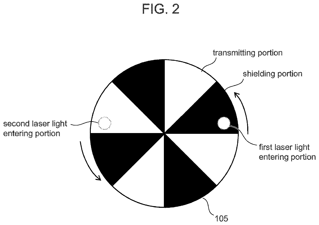
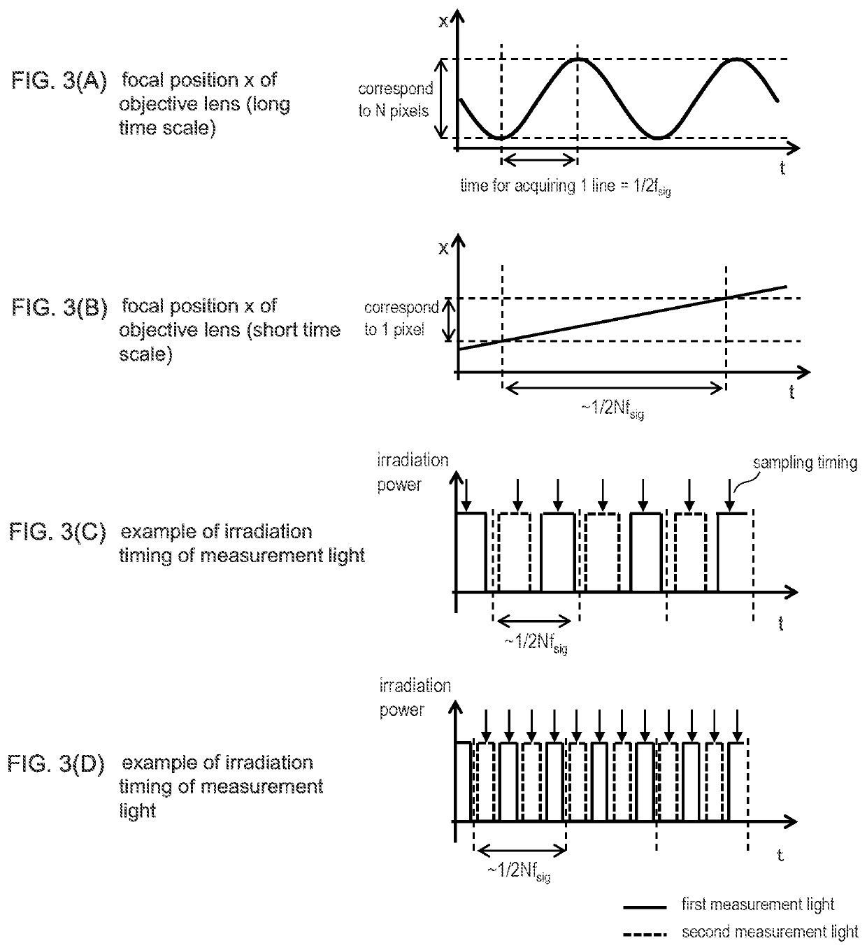
[0064]The optical image measurement apparatus according to the embodiment 1: generates the first and the second measurement light with different polarization states using the beam displacer 104, the beam displacer 104 being a passive optical element; and irradiates these measurement light alternately using the light shielding element 105 (irradiation time controller). Accordingly, it is possible to calculate the Jones matrix of the sample 110 by fewer scan (one scan) than conventional techniques without using large and expensive polarization modulation elements.
embodiment 2
[0065]FIG. 4 is a schematic diagram of a configuration example of the optical image measurement apparatus according to an embodiment 2 of the present disclosure. Same reference signs are assigned to same components as in FIG. 1, and explanations thereof will be omitted. The optical image measurement apparatus according to the embodiment 2 is different from the embodiment 1 in that two different light sources are employed. Further, the embodiment 2 is different from the embodiment 1 in that a single interference optical system is used to detect each measurement light. Other configurations are generally same as in the embodiment 1. Thus the differences will be mainly described below.
[0066]The first laser light in P polarization state emitted from the first light source 401 is converted into parallel light by a collimate lens 402. The parallel light enters a polarization beam splitter 403. The second laser light in P polarization state emitted from a second light source 404 is converte...
PUM
| Property | Measurement | Unit |
|---|---|---|
| wavelength | aaaaa | aaaaa |
| coherence length | aaaaa | aaaaa |
| optical image measurement | aaaaa | aaaaa |
Abstract
Description
Claims
Application Information
 - R&D
- Intellectual Property
- Life Sciences
- Materials
- Tech Scout
- Unparalleled Data Quality
- Higher Quality Content
- 60% Fewer Hallucinations
Browse by: Latest US Patents, China's latest patents, Technical Efficacy Thesaurus, Application Domain, Technology Topic, Popular Technical Reports.
© 2025 PatSnap. All rights reserved.Legal|Privacy policy|Modern Slavery Act Transparency Statement|Sitemap|About US| Contact US: help@patsnap.com


