
Through-air drying apparatus and methods of manufacture

a technology of through-air drying and manufacturing methods, which is applied in drying machines, lighting and heating apparatus, drying machines with progressive movements, etc., can solve the problems of limiting the possibility of over-drying the web or exceeding the ignition temperature of the web, and achieves the effect of improving the drying ra

Active Publication Date: 2020-08-18
KIMBERLY-CLARK WORLDWIDE INC
View PDF40 Cites 1 Cited by
  • Summary
  • Abstract
  • Description
  • Claims
  • Application Information

AI Technical Summary

Benefits of technology

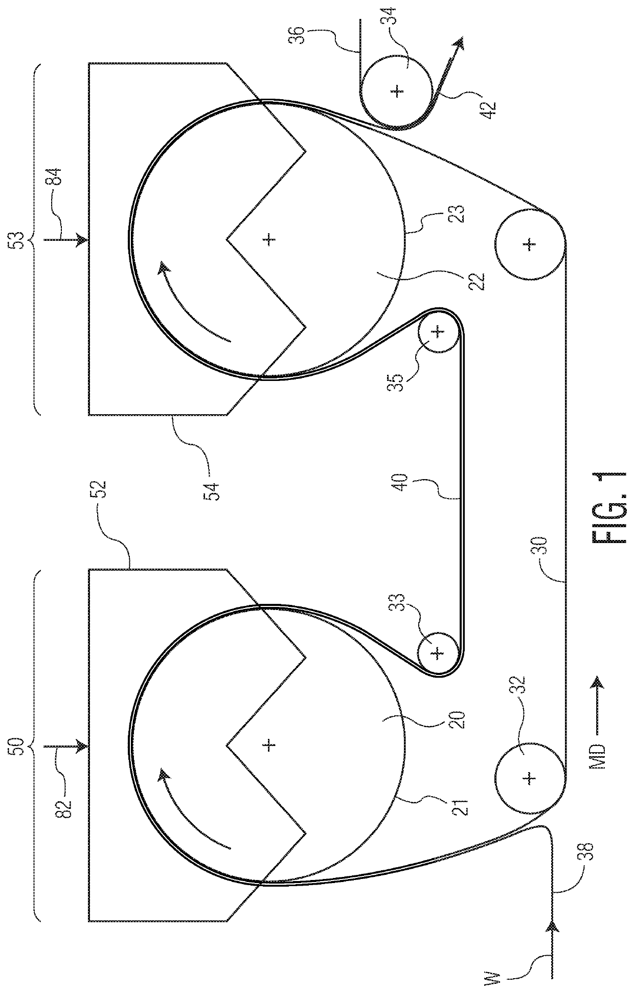
[0011]Because the web is only partially dewatered when contacted by the high temperature supply-side air the and is not fully dried as it passes over the drying apparatus the temperature of the nascent web is maintained below 450° F. (232° C.) and more preferably below 400° F. (204° C.), such as from about 200 to about 450° F. (93 to 232° C.). Further, because the partially dewatered web is supported by a fabric, particularly a polymeric fabric, as it passes over the drying apparatus not all of the heat from the high temperature supply-side air is transferred to the nascent web. Rather, a portion of the heat is transferred to the fabric and further limits the possibility of over drying the web or exceeding the webs ignition temperature. Therefore, the present invention provides a means of increasing the temperature of the supply-side air above the glass transition point of the cellulosic fibers without igniting the fibers or otherwise negatively affecting the physical properties of the fiber.
[0012]Accordingly, in certain embodiments, the present invention provides a means of increasing the efficiency of noncompressively drying a cellulosic web, such as a tissue web, without scorching or burning of the cellulosic fibers of the nascent web or otherwise negatively effecting the physical properties of the resulting tissue product. In fact, in certain instances, the present invention may be used to improve certain physical properties of the resulting tissue product. For example, the use of an elevated through-air drying temperature may improve molding of the web to the through-air drying fabric as the web is transported over the first dewatering device. The improved molding may, in-turn, improve certain physical properties of the resulting tissue web, such as sheet bulk and surface texture.
[0013]Thus, in one embodiment the present invention provides a tissue apparatus comprising at least two noncompressive dewatering devices, such as two through-air driers, where the first device is supplied with air having a temperature greater than about 450° F. (232° C.), and in certain instances greater than 475° F. (246° C.), such as from about 450 to about 700° F. (232 to 371° C.), and the second is supplied with air having a lower temperature, such as less than about 500° F. (260° C.), more preferably less than about 470° F. (243° C.) and more preferably less than 450° F. (232° C.). In this manner the invention provides a through-air drying apparatus which reduces the necessary residence time of the embryonic web thereon and / or requires less energy than had previously been thought in the prior art to dry the web to a final dryness. Further, by providing an apparatus having at least two drying zones is provided where each drying zone may be specifically adapted to maximize the efficiency of tissue web manufacture and / or maximize tissue web physical properties.

Problems solved by technology

Further, because the partially dewatered web is supported by a fabric, particularly a polymeric fabric, as it passes over the drying apparatus not all of the heat from the high temperature supply-side air is transferred to the nascent web.
Rather, a portion of the heat is transferred to the fabric and further limits the possibility of over drying the web or exceeding the webs ignition temperature.

Method used


Image

  • Through-air drying apparatus and methods of manufacture
  • Through-air drying apparatus and methods of manufacture

Examples


Embodiment Construction

[0029]It has now been discovered that the drying rate may be improved by providing a tissue making machine having two noncompressive dewatering devices, such as two through-air driers, where the supply temperature of each the devices may be separately controlled. The temperature of the air supplied to the first dewatering device may be increased to in excess of 450° F., and in certain instances greater than 500° F., such as from about 475 to about 600° F., such as from 500 to about 575° F. On the other hand the temperature of the air supplied to the second dewatering device is generally less than the temperature of the air supplied to the first. For example, if the temperature of air supplied to the first dewatering device may be increased to in excess of 550° F., the temperature of air supplied to the first dewatering device may range from 400 to 490° F.

[0030]The temperature the drying medium supplied to the first through-air dryer may exceed 450° F. so long as the sheet is only pa...


PUM


Abstract

Methods of improving the drying rate of a cellulosic web, such as a tissue web, by providing an apparatus having two noncompressive dewatering devices, such as two through-air driers, where the temperature of the drying medium supplied to each device is separately controlled. The temperature of the medium supplied to the first device may exceed 450° F., such as from about 450 to about 600° F. On the other hand the temperature of the medium supplied to the second device may be less than the temperature supplied to the first, such as from about 350 to 450° F. Drying the web in this manner not only improves drying efficiency, but also limits or prevents degradation of the web, such as the combustion of cellulosic fibers making up the web or monosaccharides associated therewith. As such, webs that are substantially free from furan and acetaldehyde may be produced by the present methods.

Description

BACKGROUND OF THE DISCLOSURE[0001]In the manufacture of paper webs, such as tissue webs, a slurry of cellulosic fibers is deposited onto a forming wire to form a wet embryonic web. The resulting wet embryonic web may be dried by any one of or combinations of known means, where each drying means may potentially affect the properties of the resulting tissue web. For example, the drying means may affect the softness, caliper, tensile strength, and absorbency of the resulting cellulosic tissue web.[0002]An example of one drying means is through-air drying. In a typical through-air drying process, a foraminous air permeable fabric supports the embryonic web to be dried. Hot air flow passes through the web, then through the permeable fabric or vice versa. The air flow principally dries the embryonic web by evaporation. Regions coincident with and deflected into fabric voids are preferentially dried. Regions of the web coincident with solid regions of the fabric, such as woven knuckles, ar...

Claims


Application Information

Patent Timeline
Patent Type & Authority Patents(United States)
IPC IPC(8): D21F1/00F26B21/10D21F11/14F26B13/16D21F5/18
CPCD21F11/14D21F5/182F26B21/10F26B13/16D21F1/0027
Inventor LAWSON, DANIEL KEITHISOM, JR., ERIC KENTZWICK, KENNETH JOHNSEYMOUR, ROBERT JAMESBESAW, CRAIG STEVENSATORI, CHRISTOPHER LEEALLEN, PETER JOHNBURAZIN, MARK ALAN
Owner KIMBERLY-CLARK WORLDWIDE INC
Learn More