
Method and device for object identification

a technology of object identification and method, applied in the field of method and device for object identification, can solve the problems of no advantage from the perspective of the self-learning machine, and achieve the effects of improving the results of object identification, increasing the capacity of the neural network, and relatively minimal complexity of individual nodes

Active Publication Date: 2020-08-04
ROBERT BOSCH GMBH
View PDF2 Cites 0 Cited by
  • Summary
  • Abstract
  • Description
  • Claims
  • Application Information

AI Technical Summary

Benefits of technology

This approach improves the robustness and accuracy of object identification by enhancing data variability and adaptability to lighting conditions, enabling more effective object recognition and tracking in both video-based monitoring and automotive applications, particularly for autonomous driving.

Problems solved by technology

As a result, however, optimizations in the image are deliberately tolerated which, though they help humans, offer no advantage from the perspective of the self-learning machine.

Method used


Image

  • Method and device for object identification
  • Method and device for object identification
  • Method and device for object identification

Examples


Embodiment Construction

[0027]In the following description of preferred exemplary embodiments of the present invention, identical or similar reference numerals are used for elements which are represented in the various figures and act similarly, a repeated description of these elements being omitted.

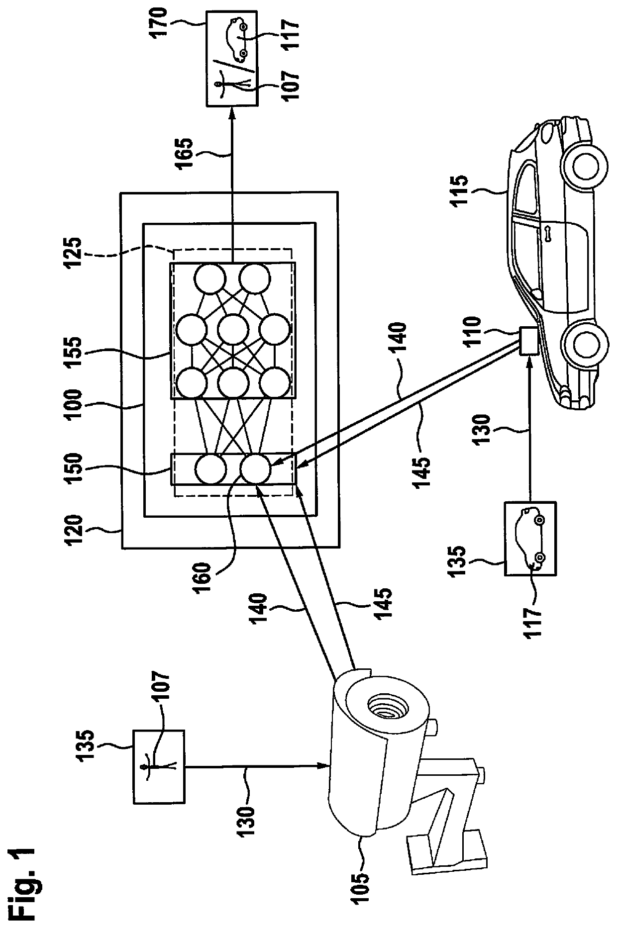
[0028]FIG. 1 schematically shows a system configuration of an object identification based on a device 100 for object identification according to one exemplary embodiment. Since the method approach presented herein may be used both in video-based monitoring technology, as well as in the automotive field, the system configuration initially includes a monitoring camera 105, which is part of a camera network according to one exemplary embodiment, and further a surroundings sensor camera 110, which is mounted as a surroundings sensor on a vehicle 115 and is used to detect surroundings of vehicle 115. The schematic system configuration further includes device 100 for object identification, which is mounted in an exte...


PUM


Abstract

A method for object identification is described, the method initially including a step of reading in, in which input data signals, as well as a determined camera control parameter for adjusting a recording feature of a camera are read in. The input data signals in this case represent the images of the object to be identified that are recorded by at least one camera. Finally, the method includes a step of identification, in which the object is identified in a neural network using the determined camera control parameter.

Description

FIELD OF THE INVENTION[0001]The present invention is directed to a device or to a method according to the definition of the species in the independent claims. The subject matter of the present invention is also a computer program.BACKGROUND INFORMATION[0002]Devices are known which identify and classify objects with the aid of neural networks.[0003]German Published Patent Application No. 10 2009 055 127 A1 describes a video monitoring system for detecting and tracking a conspicuous object, the object being detected with the aid of a detection device based on a predefined model description and being tracked over a particular period of time by a tracking device, the tracking device detecting a plurality of tracking parameters and being coupled back to the detection device, so that during repeated detection, the tracking parameters are fed to the detection device and are taken into account for detecting the object. The video monitoring system is optionally designed as a learning or self...

Claims


Application Information

Patent Timeline
Patent Type & Authority Patents(United States)
IPC IPC(8): H04N5/232G06K9/00G06K9/62H04N5/235G06V10/10G06V10/764
CPCH04N5/232G06K9/6256G06K9/6262G06K9/00624H04N5/23299H04N5/235H04N7/18H04N9/64H04N23/60H04N25/60H04N23/88G06V10/10G06V10/764H04N23/70G06F18/214G06F18/217H04N23/695
Inventor BLOTT, GREGORBORCHERS, ROBERT
Owner ROBERT BOSCH GMBH
Learn More