Controller for extending a protection period of a power converter and operational method thereof
a technology of power converter and control panel, which is applied in the direction of power conversion system, dc-dc conversion, instruments, etc., can solve the problems of damage to the components of the television, and the difficulty of effectively dissipating the heat generated by the power switch during the recovery period, so as to achieve the effect of prolonging the protection period
- Summary
- Abstract
- Description
- Claims
- Application Information
AI Technical Summary
Benefits of technology
Problems solved by technology
Method used
Image
Examples
first embodiment
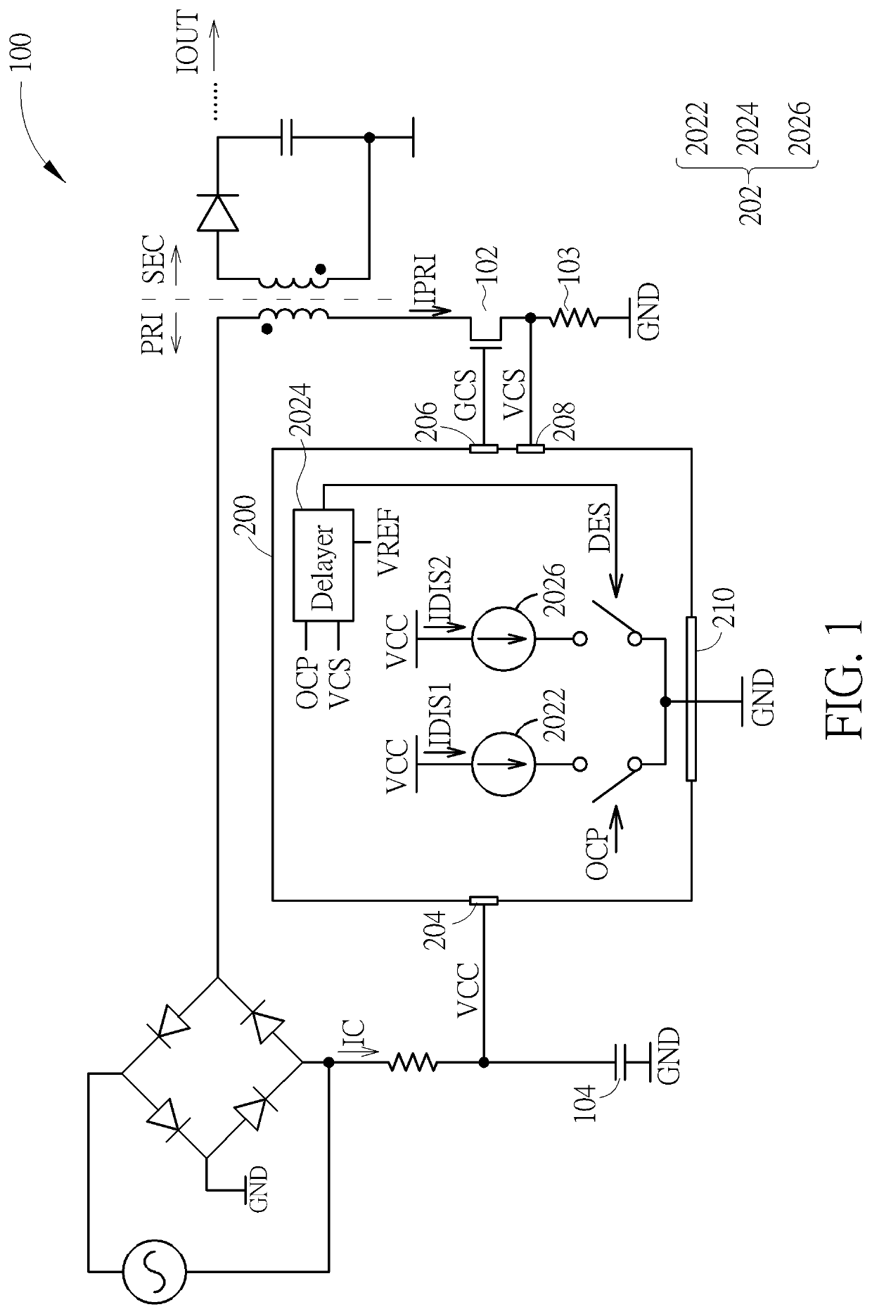
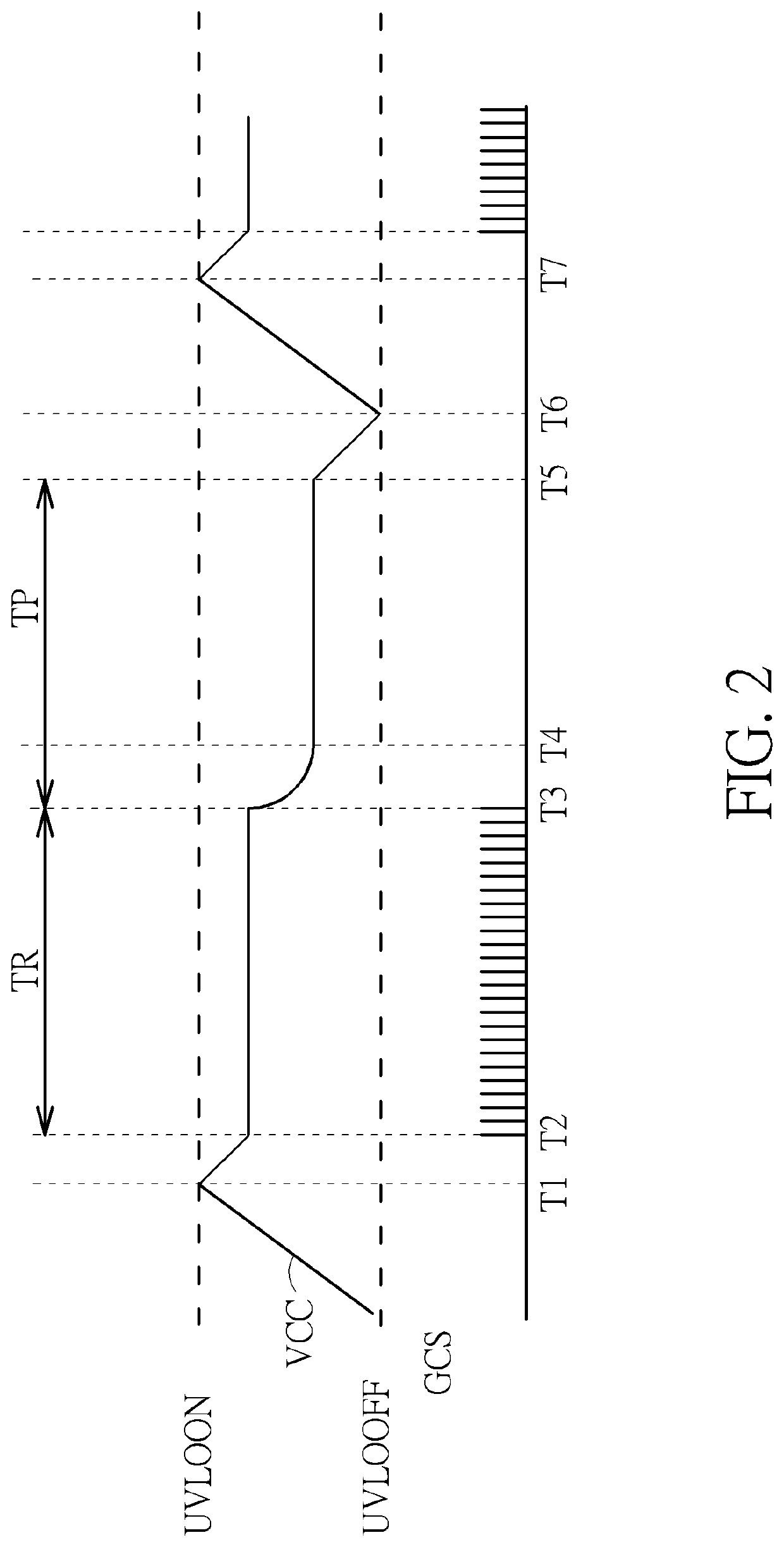
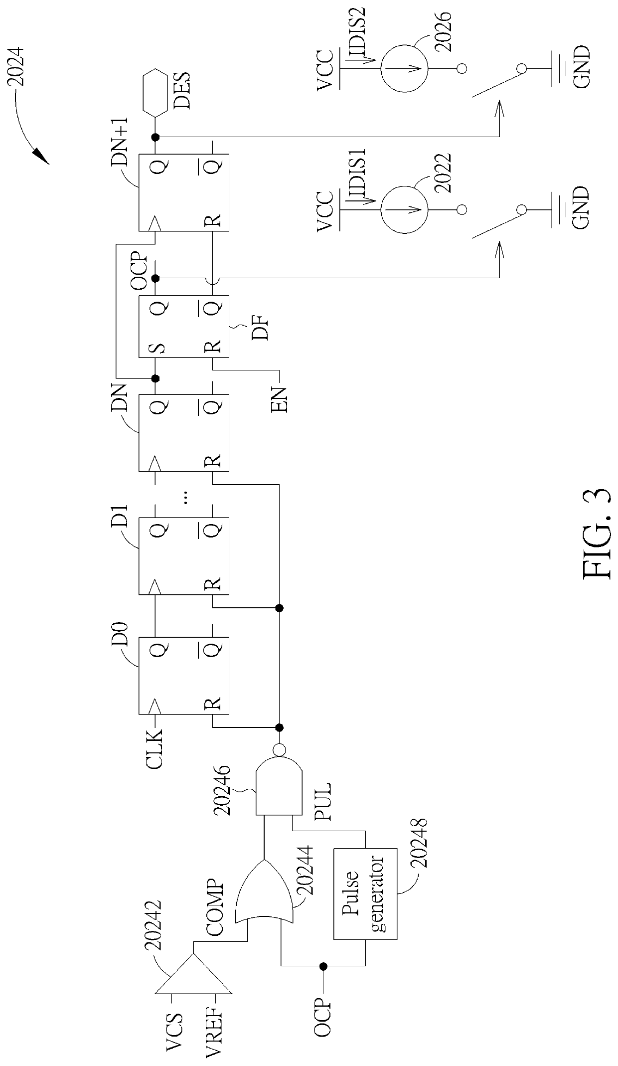
[0017]Please refer to FIG. 1. FIG. 1 is a diagram illustrating a controller 200 for extending a protection period of a power converter 100 according to the present invention, wherein the power converter 100 is a flyback power converter, and FIG. 1 only shows components of the power converter 100 and the controller 200 related to the present invention to simplify FIG. 1. As shown in FIG. 1, the controller 200 includes a delay circuit 202, and the delay circuit 202 includes a first current source 2022, a delayer 2024, and a second current source 2026, wherein the first current source 2022 is coupled to a supply voltage pin 204, the second current source 2026 is coupled to the delayer 2024 and the supply voltage pin 204, and the controller 200 receives a supply voltage VCC through the supply voltage pin 204. As shown in FIG. 1, a protection circuit (not shown in the controller 200 of FIG. 1) of the controller 200 can determine whether to make the power converter 100 enter a protection ...
second embodiment
[0022]Please refer to FIGS. 5, 6. FIG. 5 is a diagram illustrating a controller 500 for extending the protection period of the power converter 100 according to the present invention, and FIG. 6 is a timing diagram illustrating a supply voltage VCC of the controller 500 and a gate control signal GCS generated by the controller 500 after the power converter 100 enters the protection mode, wherein FIG. 5 only shows components of the power converter 100 and the controller 500 related to the present invention to simplify FIG. 5. As shown in FIG. 5, differences between the controller 500 and the controller 200 are that the controller 500 includes a delay circuit 502, and the delay circuit 502 includes a current source 5022 and a counter 5024, wherein the current source 5022 is coupled to the supply voltage pin 204, the counter 5024 is coupled to the current source 5022, and the controller 500 receives the supply voltage VCC through the supply voltage pin 204. In addition, as shown in FIG....
third embodiment
[0024]Please refer to FIGS. 1, 2, 7. FIG. 7 is a flowchart illustrating an operational method of a controller extending a protection period of a power converter according to the present invention. The operational method in FIG. 7 is illustrated using the power converter 100 and the controller 200 in FIG. 1. Detailed steps are as follows:
[0025]Step 700: Start.
[0026]Step 702: The power converter 100 enters the protection mode.
[0027]Step 704: The first current source 2022 generates the first discharge current IDIS1 according to the protection signal OCP and the supply voltage VCC.
[0028]Step 706: The delayer 2024 generates the delay enabling signal DES according to the protection signal OCP and the detection voltage VCS.
[0029]Step 708: The second current source 2026 generates the second discharge current IDIS2 according to the delay enabling signal DES.
[0030]Step 710: When the supply voltage VCC is lower than the under voltage lock out turning-off voltage UVLOOFF, the controller 200 dis...
PUM
 Abstract
Description
Claims
Application Information
 - R&D
- Intellectual Property
- Life Sciences
- Materials
- Tech Scout
- Unparalleled Data Quality
- Higher Quality Content
- 60% Fewer Hallucinations
Browse by: Latest US Patents, China's latest patents, Technical Efficacy Thesaurus, Application Domain, Technology Topic, Popular Technical Reports.
© 2025 PatSnap. All rights reserved.Legal|Privacy policy|Modern Slavery Act Transparency Statement|Sitemap|About US| Contact US: help@patsnap.com


