Safety apparatus for protecting an operator of an electrically powered saw

a safety apparatus and operator technology, applied in the field of safety equipment, can solve the problems of operator at risk of contacting the blade, serious injury including loss of digits and worse, delay involved in which significant injury can be sustained from the blade,

Active Publication Date: 2020-06-30
SCOTT AUTOMATION & ROBOTICS PTY LTD
View PDF34 Cites 0 Cited by
  • Summary
  • Abstract
  • Description
  • Claims
  • Application Information

AI Technical Summary

Benefits of technology

[0006]The present invention provides an apparatus for stopping the travel of the blade of an electrically powered saw in an emergency situation such as when the operator of the saw comes into contact with the blade of the saw or is otherwise at risk of coming into contact with the blade.
[0031]As will be appreciated, the use of an apparatus embodied by the invention may save operators from amputations or significantly lessen the seriousness of injury resulting from contact with the blade of the saw. Whilst saws to which an apparatus embodied by the invention has been fitted find particular application to the red meat processing industry, it will be understood that embodiments of the invention have broader application and the invention is not limited thereto.

Problems solved by technology

This inherently places the operator at risk of contacting the blade in the event of slipping or, for example, as a result of inattention.
Contact with the blade can result in serious injury including loss of digits and worse.
Once an operator recognizes they have come into contact with the blade and takes corrective action, there is nevertheless a time delay involved in which significant injury can be sustained from the blade.
Injuries to operators can be debilitating for the operator, distressing to all involved, and costly to employers in terms of downtime, loss of productivity and associated rehabilitation of the employee.

Method used


Image

  • Safety apparatus for protecting an operator of an electrically powered saw
  • Safety apparatus for protecting an operator of an electrically powered saw
  • Safety apparatus for protecting an operator of an electrically powered saw

Examples


Embodiment Construction

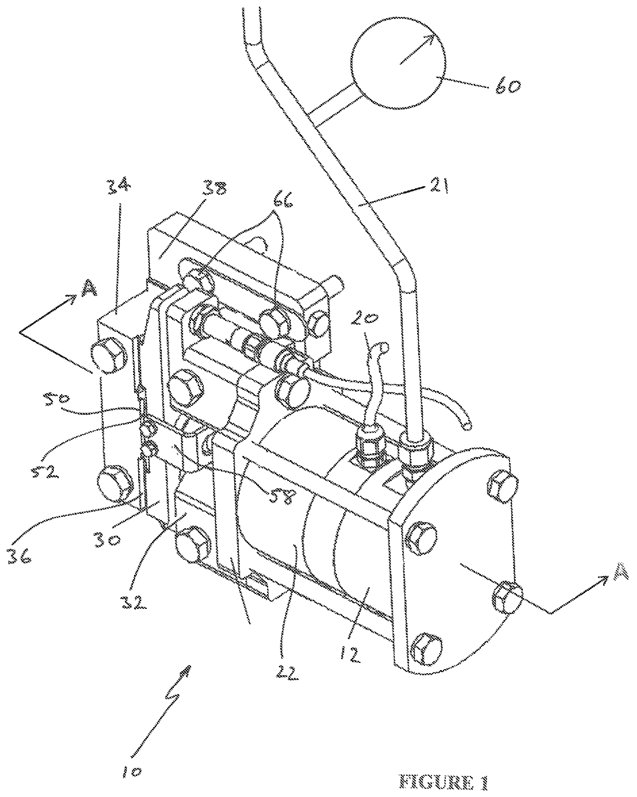
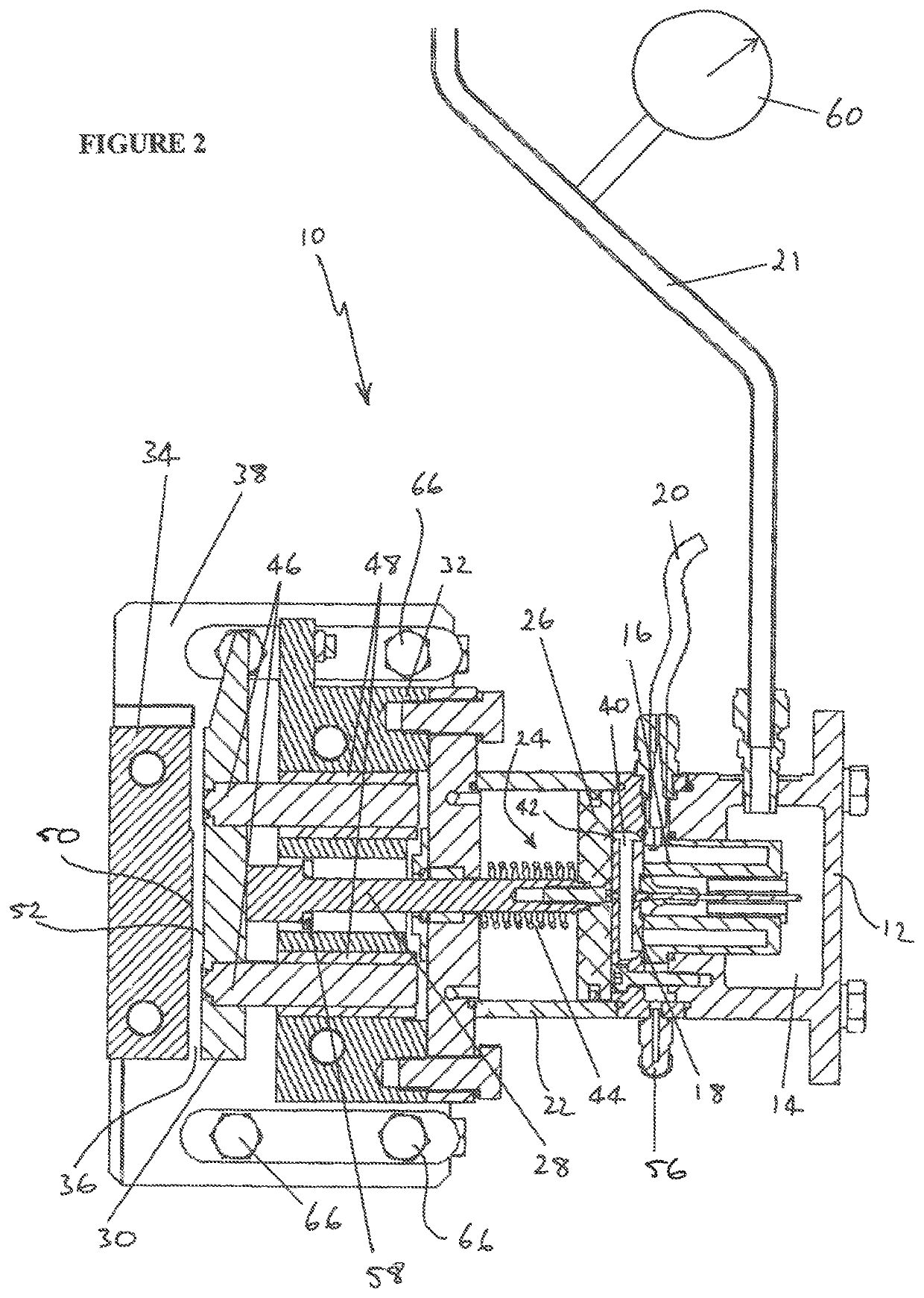
[0039]An emergency braking apparatus 10 embodied by the invention for stopping the travel of a blade of an electrically powered saw is shown in FIG. 1 and FIG. 2. As best shown in FIG. 2, the apparatus has a pressure chamber housing 12 in the form of a cylinder in which is defined a pressure chamber 14 for holding a fluid under pressure as described further below. A solenoid actuator 16 is housed by the cylinder 12 and is energised via the solenoid lead 20 in use. The solenoid actuator is a normally open solenoid valve with a plunger type valve member comprising a valve disc 18, and is operable in response to an emergency braking signal as further described below.

[0040]The fluid is fed into the pressure chamber 14 through a feed line 21 and the pressure chamber housing 12 is mounted to a piston cylinder 22 in which a driver in the form of a piston 24 is slidably arranged. The piston 24 has a piston head 26 disposed in the piston cylinder 22 and a piston rod 28 that projects from the...


PUM


Abstract

There is provided an emergency braking apparatus for stopping travel of the blade of an electrically powered saw of the type incorporating a cutting table through which the blade of the saw passes during a cutting operation. The apparatus comprises a braking jaw and a movable jaw spaced apart from the braking jaw for reception of the blade of the saw between the braking jaw and the movable jaw. The apparatus also comprises a driver for driving the movable jaw from a retracted position into contact with a side face of the blade to force an opposite side the blade against the braking jaw and thereby clamp the blade between the braking jaw and the movable jaw, a pressure chamber for holding a fluid at a predetermined pressure, and an actuator operable in response to an emergency braking signal to release the pressurised fluid in the pressure chamber to drive the driver against the movable jaw whereby the movable jaw is driven into contact with the side face of the blade.

Description

[0001]This application is a National Stage Application of PCT / AU2015 / 050561, filed 18 Sep. 2015, which claims benefit of Serial No. 2014903735, filed 18 Sep. 2014 in Australia and which applications are incorporated herein by reference. To the extent appropriate, a claim of priority is made to each of the above disclosed applications.FIELD OF THE INVENTION[0002]The present invention relates to safety apparatus for stopping the travel of the blade of an electrically powered saw to protect a user of the saw. The apparatus finds particular application to saws commonly used for the processing of meat and / or animal carcasses.BACKGROUND OF THE INVENTION[0003]Band saws are commonly used to cut carcasses and meat sections in the red meat industry as part of the meat processing stage. When using a band saw, the operator generally physically holds the carcass or meat section either side of the band saw blade and drives the meat into the blade to effect the cutting operation. This inherently p...

Claims


Application Information

Patent Timeline
Patent Type & Authority Patents(United States)
IPC IPC(8): A22C17/00B27B13/14F16P7/00B27G19/06F16P3/12B27B5/38F16P3/14
CPCB27B13/14F16P7/00F16P3/12B27B5/38A22C17/0006B27G19/06F16P3/14
Inventor CAMPBELL, CLYDE MARK
Owner SCOTT AUTOMATION & ROBOTICS PTY LTD
Why Eureka
Try Eureka