Eureka AIR delivers breakthrough ideas for toughest innovation challenges, trusted by R&D personnel around the world.

Apparatus and method for compensating a position information error of a resolver

a position information error and resolver technology, applied in the field of apparatus and methods for compensating position information errors of resolvers, can solve the problem that the position error component measured in a particular velocity cannot be used for compensation in another velocity

Active Publication Date: 2020-06-23
HYUNDAI MOTOR CO LTD
View PDF23 Cites 4 Cited by
  • Summary
  • Abstract
  • Description
  • Claims
  • Application Information

AI Technical Summary

Benefits of technology

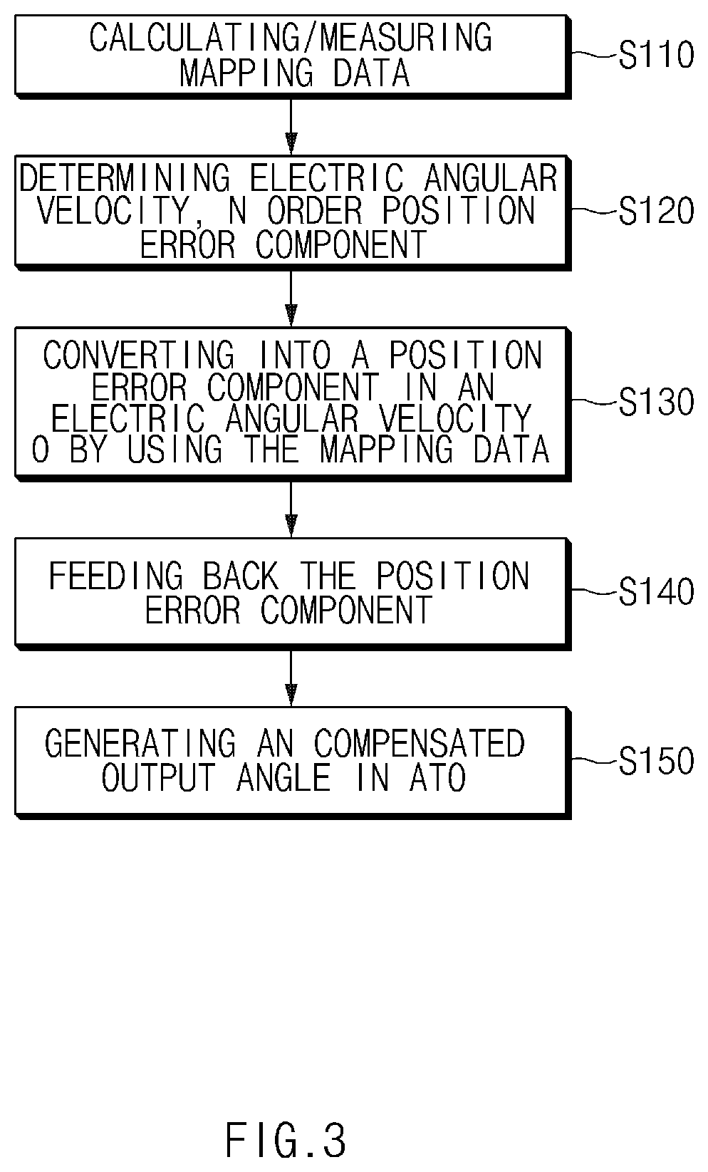
[0011]The apparatus may eliminate the error by converting an amplitude and a phase of the position error component of the resolver output signal to the position error component in the electric angular velocity 0, based on a value of the electric angular velocity, and reflecting the position error component in the electric angular velocity 0 in the resolver-digital converter.
[0022]The method may further include: eliminating the error by converting an amplitude and a phase of the position error component of the resolver output signal to the position error component in the electric angular velocity 0, based on a value of the electric angular velocity; and reflecting the position error component in the electric angular velocity 0.
[0033]Accordingly, the apparatus, method, and computer readable medium for compensating for a position information error of a resolver according to the present disclosure can provide accurate output angle information without compensating for the position error based on each velocity for each of information digitally converted in a RDC chip implemented by HW or a RDC function implemented by S / W, etc., by inputting a previously calculated position error compensation result to an ATO input.

Problems solved by technology

However, if the position information measured in the resolver has an error, compensation can be performed by using a recursive least squares (RLS) adaptive filter or the like.
Thus, there is a problem in which the position error component measured in a particular velocity cannot be used for compensation in another velocity.

Method used


Image

  • Apparatus and method for compensating a position information error of a resolver
  • Apparatus and method for compensating a position information error of a resolver
  • Apparatus and method for compensating a position information error of a resolver

Examples


Embodiment Construction

[0038]Hereinafter, the present disclosure will be described in detail with reference to the drawings. At this time, in each of the drawings, the same components are denoted by the same reference symbols, if possible. Further, detailed descriptions for the previously known features and / or configurations are omitted. In the description below, parts required to understand operations in accordance with various embodiments will be explained in priority, the descriptions for elements, which may obscure the gist of the descriptions, are omitted. It can also be shown schematically some of the elements in the figures are exaggerated or omitted. Not utterly reflect an actual size to the size of each element, so that they are not intended to limit the content that is specified here by the relative size and spacing of the elements drawn in the figure, respectively.

[0039]The terminology used herein is for the purpose of describing particular embodiments only and is not intended to be limiting of...


PUM


Abstract

An apparatus for compensating for a position information error of a resolver includes: a resolver-digital converter configured to generate a corresponding output angle by estimating resolver position information from a resolver output signal; and a position error compensation learner configured to determine a position error component in a corresponding electric angular velocity of the resolver output signal using the resolver output signal and the output angle and to convert the position error component to a position error component in an electric angular velocity 0. The resolver-digital converter compensates for an error by reflecting the position error component in the electric angular velocity 0 in the error between a position angle of the resolver output signal and the output angle.

Description

CROSS-REFERENCE TO RELATED APPLICATION[0001]This application is based on and claims priority to Korean Patent Application No. 10-2014-0142095, filed on Oct. 20, 2014 in the Korean Intellectual Property Office, the disclosure of which is incorporated herein in its entirety by reference.BACKGROUNDTechnical Field[0002]The present disclosure relates to an apparatus and method for compensating a position information error of a resolver, and more particularly, an apparatus and method for compensating a position information error of a resolver in order to solve a problem in which a position error changes for each velocity depending on an angle tracking observer (ATO) characteristic.Description of the Related Art[0003]Generally, for accurate velocity control of a motor, such as a permanent magnet synchronous motor (PMSM), etc., position information measured in a resolver (i.e., a rotor position sensor of a motor) is used. However, if the position information measured in the resolver has an ...

Claims


Application Information

Patent Timeline
Patent Type & Authority Patents(United States)
IPC IPC(8): G01D18/00G01D5/20G01D5/244
CPCG01D5/2449G01D5/2046G01D18/002G01R35/00H02P6/16
Inventor PARK, JOO YOUNGIHM, HYUNG BINYANG, BYUNG HOON
Owner HYUNDAI MOTOR CO LTD
Why Eureka
Eureka Blog
Learn More