
Finite element modeling and analysis of crack propagation in multiple planes of a structure

a technology of finite element and structure, applied in the field of numerical modeling and analysis, can solve the problems of hampered prediction of crack initiation and propagation in a material using existing finite element computer modeling techniques, limitations of techniques, and inability to predict crack propagation in two or three planes of a structur

Active Publication Date: 2020-06-02
THE BOEING CO
View PDF4 Cites 0 Cited by
  • Summary
  • Abstract
  • Description
  • Claims
  • Application Information

AI Technical Summary

Benefits of technology

This approach enables efficient prediction of crack propagation in structures with multiple planes, reducing the need for multiple computer runs and simplifying post-processing, while accurately modeling crack behavior under external loads.

Problems solved by technology

However, existing finite element modeling and analysis techniques are not readily able to predict the initiation and propagation of cracks in two or three planes of a structure.
In particular, the prediction of crack initiation and propagation in a material using existing finite element computer modeling techniques has been hampered by a number of limitations of the techniques.
The existing techniques are not able to easily predict the initiation or propagation of cracks in structures containing material or geometric non-linearities or exhibiting non-linear material or geometric response (e.g., as a result of large displacements).
Further, some of these techniques require multiple computer runs to propagate the crack which results in tedious post-processing of multiple finite element solutions.

Method used


Image

  • Finite element modeling and analysis of crack propagation in multiple planes of a structure
  • Finite element modeling and analysis of crack propagation in multiple planes of a structure
  • Finite element modeling and analysis of crack propagation in multiple planes of a structure

Examples


Embodiment Construction

[0025]Some implementations of the present disclosure will now be described more fully hereinafter with reference to the accompanying drawings, in which some, but not all implementations of the disclosure are shown. Indeed, various implementations of the disclosure may be embodied in many different forms and should not be construed as limited to the implementations set forth herein; rather, these example implementations are provided so that this disclosure will be thorough and complete, and will fully convey the scope of the disclosure to those skilled in the art. For example, unless otherwise indicated, reference to something as being a first, second or the like should not be construed to imply a particular order. Also, for example, reference may be made herein to quantitative measures, values, relationships or the like (e.g., planar, coplanar, perpendicular). Unless otherwise stated, any one or more if not all of these may be absolute or approximate to account for acceptable variat...


PUM


Abstract

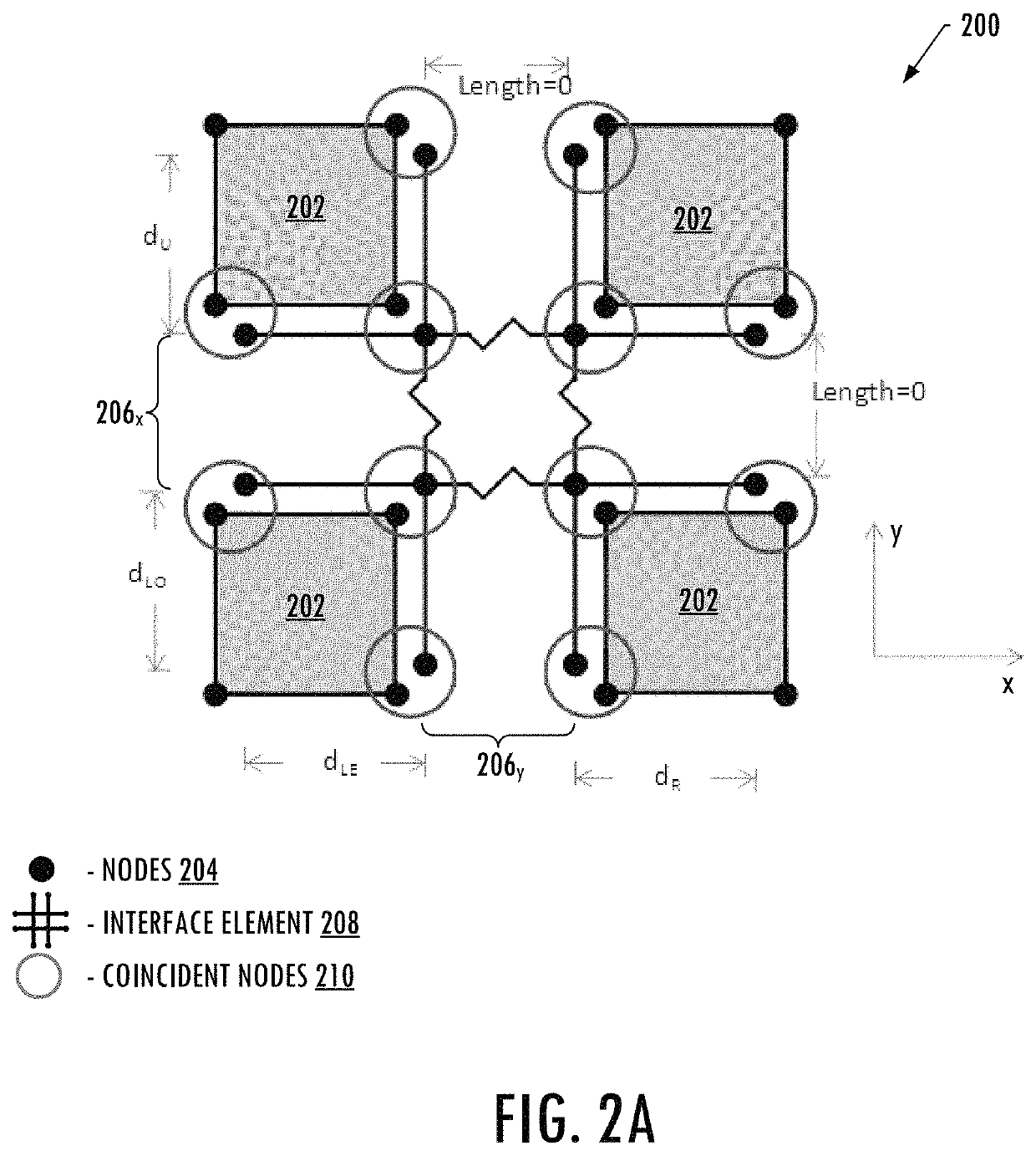
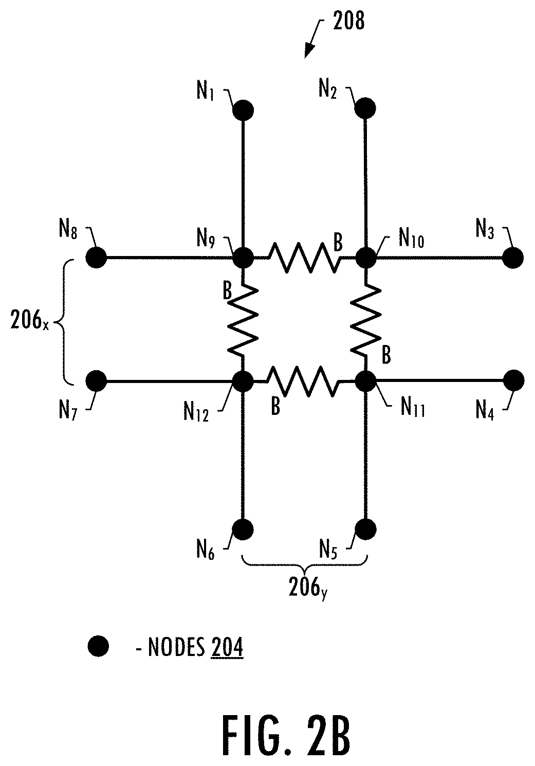
An apparatus is provided for predicting propagation of a crack in a structure. A finite element model is provided that represents the layers of the structure by meshes of elements having interfaces defined between adjacent elements in orthogonal potential crack planes. Overlapping interface elements are defined at the interfaces and include a plurality of node pairs spaced apart along multiple interfaces and having a node cluster therebetween that includes bound node pairs. The nodes of each node pair are coincident with respective nodes of the adjacent elements on opposite sides of the interface. An analysis of the finite element model under an external load is performed in which a crack tip is established at a node cluster. A strain energy release rate between the nodes of the bound node pairs of the node cluster is calculated and based thereon propagation of the crack is identified.

Description

TECHNOLOGICAL FIELD[0001]The present disclosure relates generally to numerical modeling and analysis and, in particular, finite element modeling and analysis for predicting propagation of a crack in and throughout multiple planes of a structure including a plurality of layers.BACKGROUND[0002]Numerical modeling and analysis technology is an important tool in the design and verification of many engineered structures and the structural components of which they are composed. One common computer-based numerical modeling and analysis technique is finite element modeling and analysis. In accordance with various numerical modeling analysis techniques, computer models may define a working environment in terms of geometry, elements, properties, loads, constraints and the like, and can thus be solved and analyzed to determine structural integrity of an engineered structure within that working environment, for example. Through numerical modeling and analysis and in particular finite element ana...

Claims


Application Information

Patent Timeline
Patent Type & Authority Patents(United States)
IPC IPC(8): G06F30/15G06F30/23G06F30/20G06F113/26
CPCG06F30/20G06F30/15G06F30/23G06F2113/26G06F2111/10
Inventor MABSON, GERALD E.RAMNATH, MADHAVADASWILKINSON, MARIANNE E.
Owner THE BOEING CO
Learn More