Steering column assembly

a technology for steering columns and assemblies, applied in steering columns, steering parts, vehicle components, etc., can solve the problems of limited friction, high bolt tension, and permanent damage to the tips of teeth, so as to reduce the resistance of movement and limit friction

Active Publication Date: 2020-05-26
TRW LIMITED
View PDF30 Cites 0 Cited by
  • Summary
  • Abstract
  • Description
  • Claims
  • Application Information

AI Technical Summary

Benefits of technology

[0021]By providing a biasing spring, the toothed block is able to be biased such that, when in the unclamped position, it is urged to a position in which, when clamped, it will be engage the teeth of the first side of the slot without requiring lateral movement during a collapse, and / or when in the clamped position within the slot, it is urged into engagement with the teeth of the first side of the slot. This provides an additional feature which ensures that the toothed block is in an optimum position to engage the teeth of the first side of the slot as soon as possible during a crash. The biasing spring may also prevent or limit rattle of the carrier element, giving a quality feel to the user.
[0026]In one arrangement, the biasing spring may be housed and / or retained within a spring housing. The spring housing can therefore provide protection and / or wear resistance to the spring and / or to components that would otherwise by in contact with the spring. It may also be used to aid the assembly of the device.
[0029]The at least one retaining element may be receivable within a corresponding aperture in the biasing spring. Additionally, the at least one retaining element may include a chamfer angled such that it faces in the direction. in which the biasing spring is introduced, during assembly. The chamfer allows, during assembly, the biasing spring to be pushed over the retaining element relatively easily, whilst making it difficult to remove the biasing spring in the opposite direction, once in position.
[0031]The spring housing may include a low-friction surface on a portion that contacts the inner shroud. The low-friction surface reduces resistance of movement between the spring housing and the guiding surface of the inner shroud. Thus, friction may be limited even though a biasing force is present normal to the inner shroud. Alternatively or additionally, the guiding portion of the inner shroud itself may include a low-friction surface on the portion that contacts the spring housing.

Problems solved by technology

For this, friction alone is often insufficient, as massive clamp forces would be needed to achieve this.
There is a well-known problem with the type of “Positive-Locking” column which uses rows of inter-engaging teeth whereby, prior to operation of the locking lever by the driver, the selected steering wheel axial position has resulted in exact alignment of the tips of one row of teeth with the tips of the set of teeth with which they are supposed to engage.
Inter-engaging of the teeth during the clamping operation is thereby blocked and, if excessive force is applied by the driver to the clamp lever to force it to complete its travel, permanent damage can occur to the tips of the teeth at high bolt tensions.
Unless special means are provided to overcome this problem, then it is likely to occur occasionally during adjustments.
This is undesirable.

Method used


Image

  • Steering column assembly
  • Steering column assembly
  • Steering column assembly

Examples


Embodiment Construction

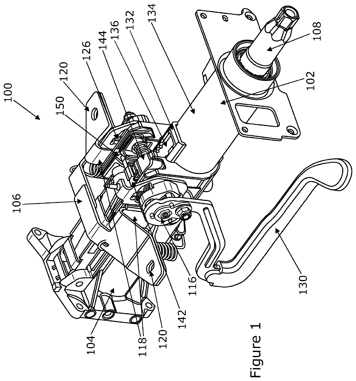
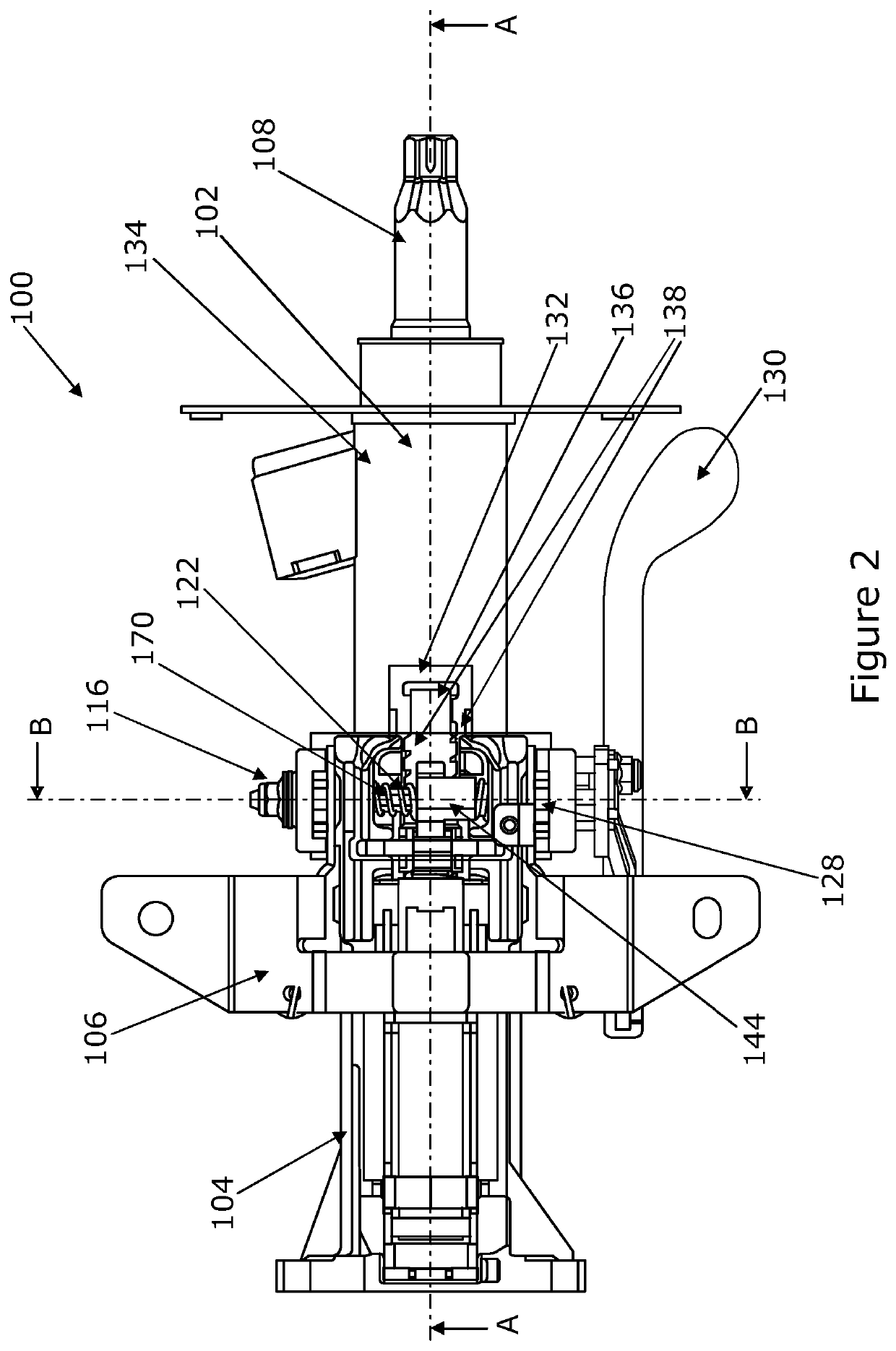
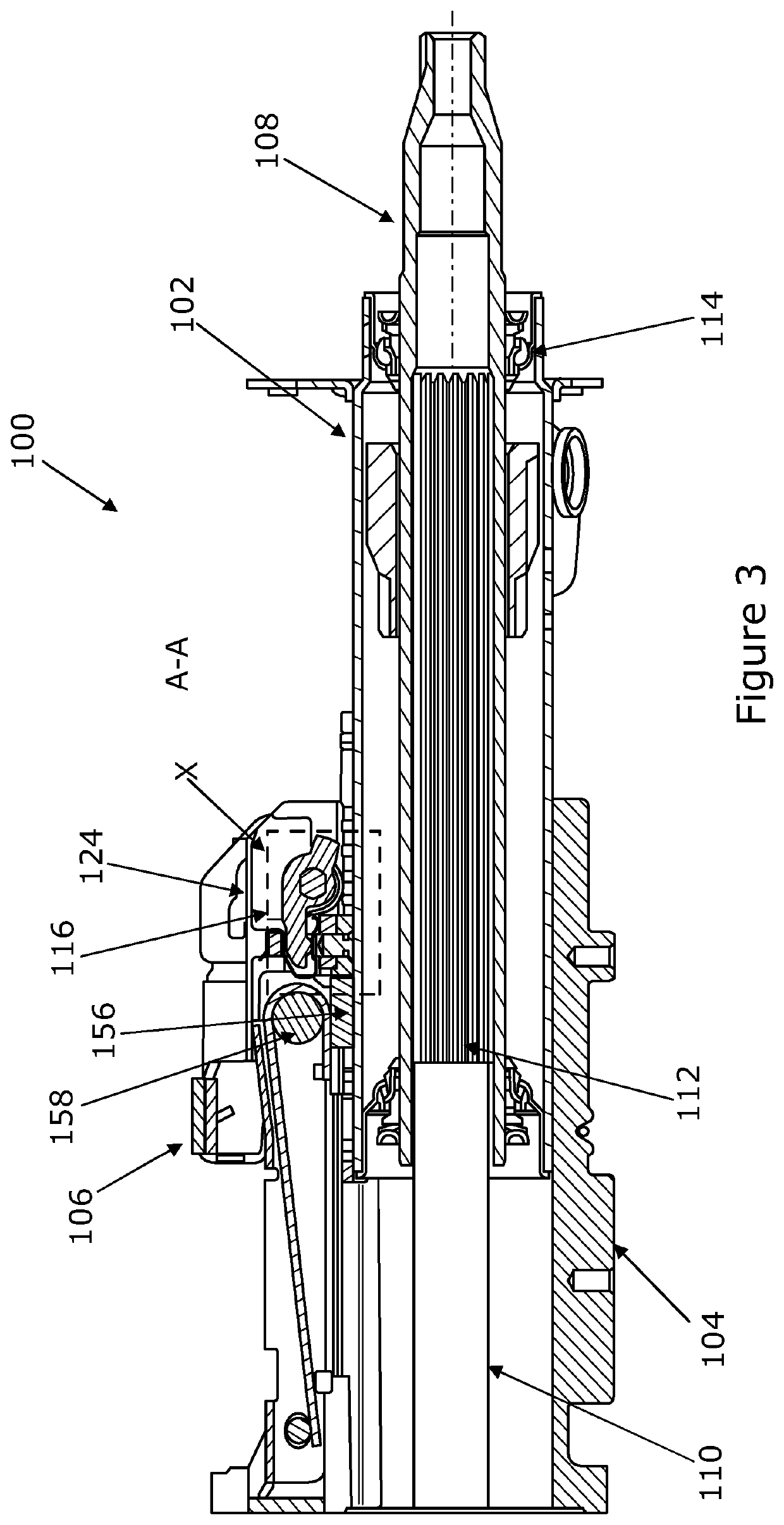
[0044]Referring first to FIGS. 1 to 3, a steering column assembly 100 is shown, in accordance with the first aspect of the invention. The steering column assembly 100 comprises a shroud having an inner shroud portion 102 and an outer shroud portion 104, each of which comprises a substantially cylindrical tube. The shroud portions 102, 104 extend from a gearbox housing (not shown) that is fixed at a pivot point to a part of the vehicle body and also fixed to a support bracket 106 which is secured to the vehicle, typically by bolting it to a region under the dashboard at a point somewhere between the pivot and the steering wheel.

[0045]The shroud portions 102, 104 are moveable relative to each other with the end of the inner shroud portion 102 being a sliding fit within an end of the outer shroud portion 104. The shroud 102, 104 surrounds a telescopic steering column shaft, formed of two shaft 108, 110. The shafts includes an upper shaft portion 108 that at least partially surrounds a ...


PUM


Abstract

A steering column assembly is provided that includes an inner shroud portion and an outer shroud portion, the inner shroud portion extending into the outer shroud portion and including a rail. The rail includes a slot with two opposing sides, each of which has teeth. A toothed block is provided that engages with the teeth of the slot, when a clamping mechanism is actuated. The toothed block is supported by a carrier that allows the toothed block to be free to move from side-to-side when engaged with the slot, and the teeth of the slot and the toothed block are shaped such that the toothed block may engage the teeth of the slot at any position when the clamping mechanism is actuated. The teeth of a first side of the slot prevent the block from moving in a collapse direction of the assembly and the teeth of the second side of the slot permit movement in a collapse direction but apply a thrust towards the teeth of the first side. The carrier includes a biasing spring that urges the toothed block towards the first side of the slot.

Description

CROSS-REFERENCE TO RELATED APPLICATIONS[0001]This application is a national stage of International Application No. PCT / GB2017 / 052790, filed Sep. 20, 2017, the disclosures of which are incorporated herein by reference in entirety, and which claimed priority to Great Britain Patent Application No. 1616323.0, filed Sep. 26, 2016, the disclosures of which are incorporated herein by reference in entirety.BACKGROUND TO THE INVENTION[0002]This invention relates to improvements in steering column assemblies. More particularly, the invention relates to steering column assemblies including a positive locking system provided by the interaction between a toothed block and a rack.[0003]It is known to provide a collapsible steering column assembly comprising a steering shaft that is supported within a steering column shroud. To prevent significant injury to the driver in the event of a crash the steering column should be able to collapse as an axial load is applied through the steering wheel, for...

Claims


Application Information

Patent Timeline
Patent Type & Authority Patents(United States)
IPC IPC(8): B62D1/19B62D1/185B62D1/184B62D1/187
CPCB62D1/192B62D1/185B62D1/187B62D1/184
Inventor DAVIES, NICLAS
Owner TRW LIMITED
Why Eureka
Try Eureka