
Reflecting sound from acoustically reflective video screen

a technology of video screen and sound, applied in the direction of transducer details, electrical transducers, electrical apparatus, etc., can solve the problems of no longer being placed behind the large video panel, unable to reflect sound, and producing superior video

Active Publication Date: 2020-04-28
DTS
View PDF11 Cites 6 Cited by
  • Summary
  • Abstract
  • Description
  • Claims
  • Application Information

AI Technical Summary

Problems solved by technology

These panels produced superior video, but were no longer transparent to audio.
Speakers could no longer be placed behind these large video panels.

Method used


Image

  • Reflecting sound from acoustically reflective video screen
  • Reflecting sound from acoustically reflective video screen

Examples


Embodiment Construction

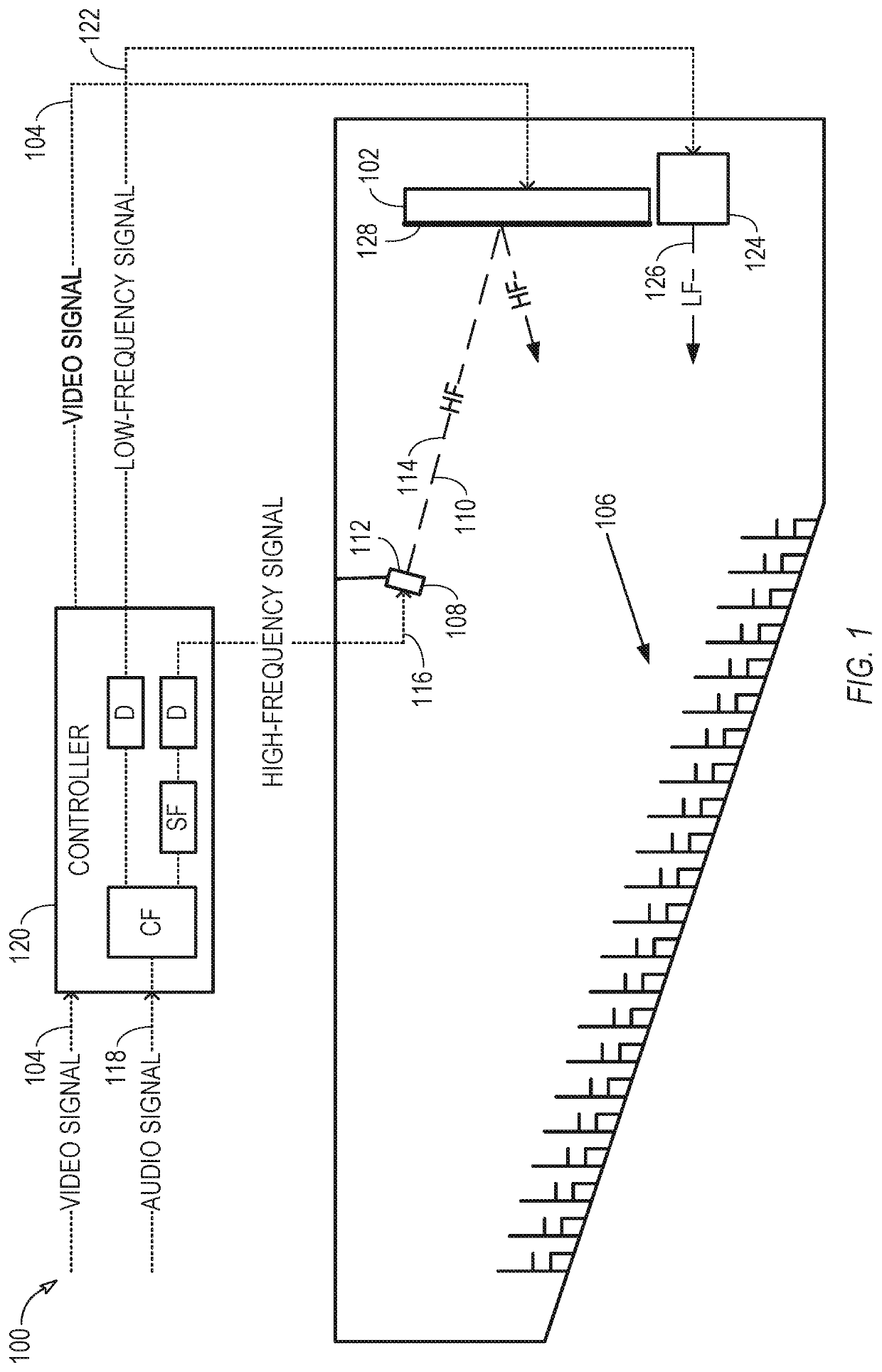
[0007]In an audiovisual system, in which video is displayed on a screen that does not permit sound to pass through the screen, such as a light emitting diode panel, an elevated speaker positioned above an audience seating area can direct sound toward the screen, so that the screen can reflect the sound toward the audience seating area. Compared to a system in which a speaker is mounted above the screen and directs its sound directly toward the audience, the reflecting geometry can lower the height from which the sound appears to originate, which can help produce a more realistic audio image at the audience seating area.

[0008]The elevated speaker can be a high-frequency speaker, which can produce sound with frequencies above a particular crossover frequency. (Note that audio crossovers can split an audio signal into two or more frequency ranges that correspond to frequency ranges for which particular speakers are designed. For example, an audio crossover can filter out relatively hig...


PUM


Abstract

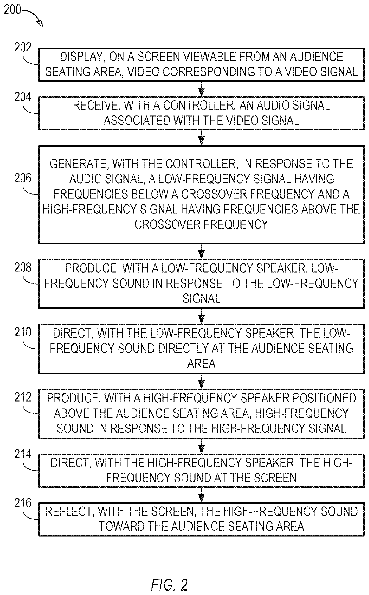
In an audiovisual system, in which video is displayed on a screen that does not permit sound to pass through the screen, such as a light emitting diode panel, a high-frequency speaker positioned above an audience seating area can direct sound toward the screen, so that the screen can reflect the sound toward the audience seating area. The high-frequency speaker can be used with one or more low-frequency speakers positioned at or near the height of the audience seating area. The low-frequency and high-frequency sounds can appear to originate from close to the same height, thereby creating a realistic audio image at the audience seating area. A spectral filter can negate the spectral effects of propagation to and reflection from the screen. Suitable time delays can synchronize the high-frequency sound with the low-frequency sound and with video displayed on the screen.

Description

FIELD OF THE DISCLOSURE[0001]The present disclosure relates to audiovisual systems and methods.BACKGROUND OF THE DISCLOSURE[0002]Historically, audiovisual systems in a theater or auditorium setting used a screen that reflected video, but was essentially transparent to audio. In these systems, speakers could be placed behind the screen, and sound from the speakers would pass through the screen to an audience seating area.[0003]As video technology evolved, it became practical to use large panels that emit light directly to the audience seating area, such as light emitting diode panels. These panels produced superior video, but were no longer transparent to audio. Speakers could no longer be placed behind these large video panels.BRIEF DESCRIPTION OF THE DRAWINGS[0004]FIG. 1 shows a side view of an example of an audiovisual system, in accordance with some embodiments.[0005]FIG. 2 shows a flowchart of an example of a method for using an audiovisual system, in accordance with some embodi...

Claims


Application Information

Patent Timeline
Patent Type & Authority Patents(United States)
IPC IPC(8): H04R1/34H04R1/26H04R3/14H04R3/04
CPCH04R3/04H04R3/14H04R1/26H04R1/345H04R2499/15H04R2201/021
Inventor SLACK, BRIAN
Owner DTS
Learn More