
Systems and methods for wind turbine circuit breaking

a technology of circuit breakers and wind turbines, applied in the field of wind turbines, can solve the problems of high currents of circuit breakers on the low-voltage side of turbine transformers, impracticality, and expensive special designs for circuit breakers, and achieve the effects of increasing the impedance of transformers, saving configuration, and increasing redundancy

Active Publication Date: 2020-04-28
SIEMENS GAMESA RENEWABLE ENERGY SERVICE GMBH
View PDF22 Cites 3 Cited by
  • Summary
  • Abstract
  • Description
  • Claims
  • Application Information

AI Technical Summary

Benefits of technology

The present invention provides an improved distribution system for a wind turbine that reduces the current that each power circuit breaker needs to handle, and ensures that no dynamic overloading occurs during switchover. This is achieved by providing separate low-voltage windings for each power circuit breaker, which act on a common medium-voltage winding. The use of separate transformers for each feed line provides a compact, cost-saving configuration, but also provides added redundancy and reduces the risk of failure. The absence of cross-connection between the feed lines ensures that no current can flow out of one feed line through the other, increasing the safety and reliability of the system. The transformers associated with the feed lines are sized equally, which prevents uneven loading and improves the overall reliability of the wind turbine.

Problems solved by technology

In this case, it is problematic that the circuit breakers on the low-voltage side of the turbine transformer have quite high currents.
In the case of the wind turbine power levels of several megawatts which are now being achieved, this sometimes makes expensive special designs necessary for the circuit breakers.
However, this has proven to be impractical due to the upper limits for voltages which are defined in relevant standards; thus, they still fall into the low-voltage range.
However, this has proven to be insufficiently operationally reliable in the case of switchover.
Due to structural tolerances, it is practically unavoidable that one of the two circuit breakers switches faster than the other; thus, in the interim, the entire current flows via only a single circuit breaker.
This circuit breaker thereby becomes overloaded.
This problem has a particularly unfavorable effect in the case of a short circuit, if the highest current load occurs.
As a result, this means that precisely in the situation when the circuit breakers are needed (for example, in a short circuit), there is a high probability that they will fail due to overloading.
This is unsatisfactory.

Method used


Image

  • Systems and methods for wind turbine circuit breaking
  • Systems and methods for wind turbine circuit breaking
  • Systems and methods for wind turbine circuit breaking

Examples


Embodiment Construction

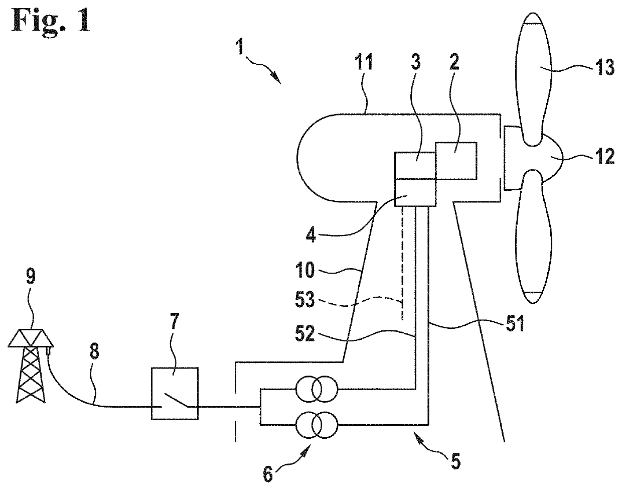
[0022]A wind turbine according to one exemplary embodiment of the present invention, which is referred to in its entirety by the reference numeral 1, comprises a nacelle 11 which is pivotably arranged on the upper end of a tower, on the front side of which a wind rotor 12 having multiple rotor blades 13 is rotatably arranged. Via a rotor shaft (not depicted), the wind rotor 12 drives a generator 2 which converts the mechanical power supplied by the wind rotor 12 into electric power and outputs it via a converter 3. At the output of the converter 3, a power circuit breaker unit 4 is arranged which, in the depicted exemplary embodiment, comprises a first power circuit breaker 41 and a second power circuit breaker 42. From there, the electric power is supplied at a low-voltage level via feed lines 5 to a turbine transformer 6. The turbine transformer 6 is designed to raise the electric power supplied at the low-voltage level to a medium-voltage level and to output it via a medium-volta...


PUM


Abstract

A wind turbine includes a wind rotor, a generator, and a converter. The generated electric power is fed from the converter by means of a feed to a turbine transformer for delivery to a grid. The feed is designed as a double branch including a power-branched power circuit breaker unit having a first feed line and a second feed line connected in parallel, wherein a separate low-voltage winding of the turbine transformer and a separate power circuit breaker at the connector of the converter is associated with each feed line.

Description

CROSS-REFERENCE TO RELATED APPLICATIONS[0001]This application claims the priority of German Application No. 10 2017 003 078.2, filed Mar. 30, 2017, the entire contents of which are incorporated herein by reference.FIELD OF THE INVENTION[0002]The present invention relates to a wind turbine comprising a wind rotor, a generator, and a converter, for generating electric power which is delivered to a grid via a turbine transformer.BACKGROUND OF THE INVENTION[0003]Modern wind turbines are capable of generating a considerable amount of electric power. They typically have power ratings of several megawatts. The electric power generated by the wind turbine is generally raised to a higher voltage level (usually a medium-voltage level) which is more suitable for transmission, via a transformer which is associated with the wind turbine (turbine transformer). For protecting the wind turbines and the grid, circuit breakers are required on both sides of the turbine transformer. In this case, it is...

Claims


Application Information

Patent Timeline
Patent Type & Authority Patents(United States)
IPC IPC(8): H02J3/38F03D9/25H02P9/10F03D80/80H02P101/15
CPCF03D9/255H02J3/38H02P9/107F03D80/85H02P2101/15Y02E10/725F05B2220/706Y02E10/763H02J3/005H02J2300/28H02J3/381Y02E10/76Y02E10/72
Inventor LETAS, HEINZ-HERMANN
Owner SIEMENS GAMESA RENEWABLE ENERGY SERVICE GMBH
Learn More