
Bearing element and bearing

a technology of bearing elements and bearings, applied in the field of bearings, can solve the problems of affecting so as to reduce load on elastomeric elements, and improve the service life of bearing elements.

Active Publication Date: 2020-04-28
SUMITOMO RIKO CO LTD
View PDF20 Cites 0 Cited by
  • Summary
  • Abstract
  • Description
  • Claims
  • Application Information

AI Technical Summary

Benefits of technology

The present invention is about a bearing element that reduces the load on the elastomeric element, which is used to transfer forces. By doing so, the service life of the bearing element is increased. This is because the support arm of the elastomeric element is put under load primarily by thrust, which results in fewer local extension peaks and a more uniform force distribution. The bearing element is useful for connecting components that absorb forces, such as cooling modules for vehicles, to other parts that are not subjected to vibrations. The elastomeric element is made of rubber or a similar material and can decouple the component from vibrations and take up a force from the component. The inner connection between the component and the elastomeric element can be a sleeve or an axial recess in the elastomeric element. The support pin is a rigid connecting device for connecting to the bearing element. Overall, this invention improves the load-carrying capacity and service life of the bearing element.

Problems solved by technology

The bearing element may be deformed so strongly by these forces, that the bearing element strikes against a bearing or vehicle frame, so that a proper decoupling of cooling module and vehicle frame no longer is ensured.
Because of contact between the bearing element and the bearing or vehicle frame, there may be unpleasant vibrations and noises.
Because of the large deformation, an elastomeric element of the bearing element may be damaged.
In the case of known bearing elements and at such large displacements or forces, high extensions, especially extension peaks, which may lead to the failure of the elastomeric elements, usually occur in the elastomeric elements.

Method used


Image

  • Bearing element and bearing
  • Bearing element and bearing
  • Bearing element and bearing

Examples


Embodiment Construction

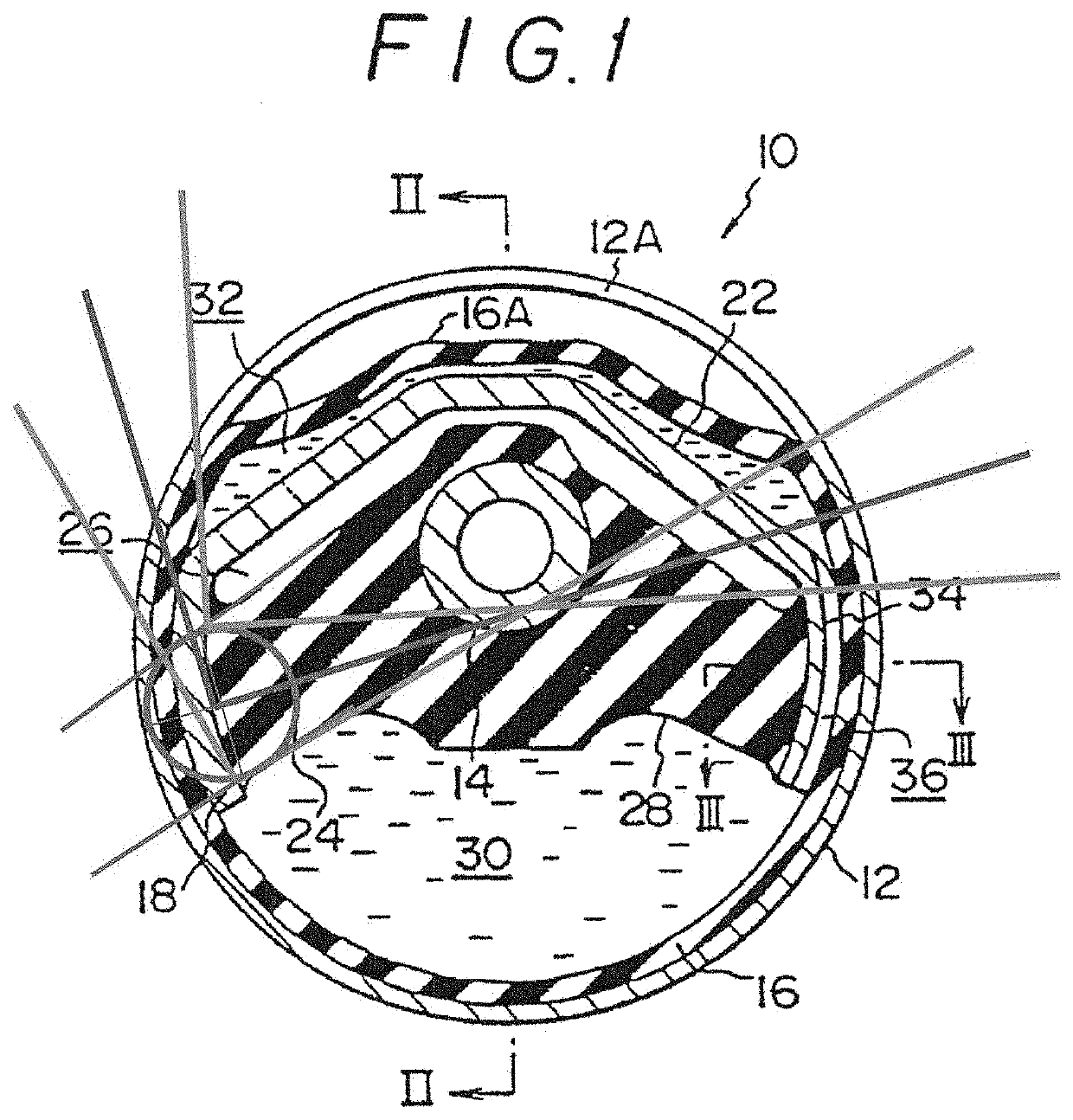
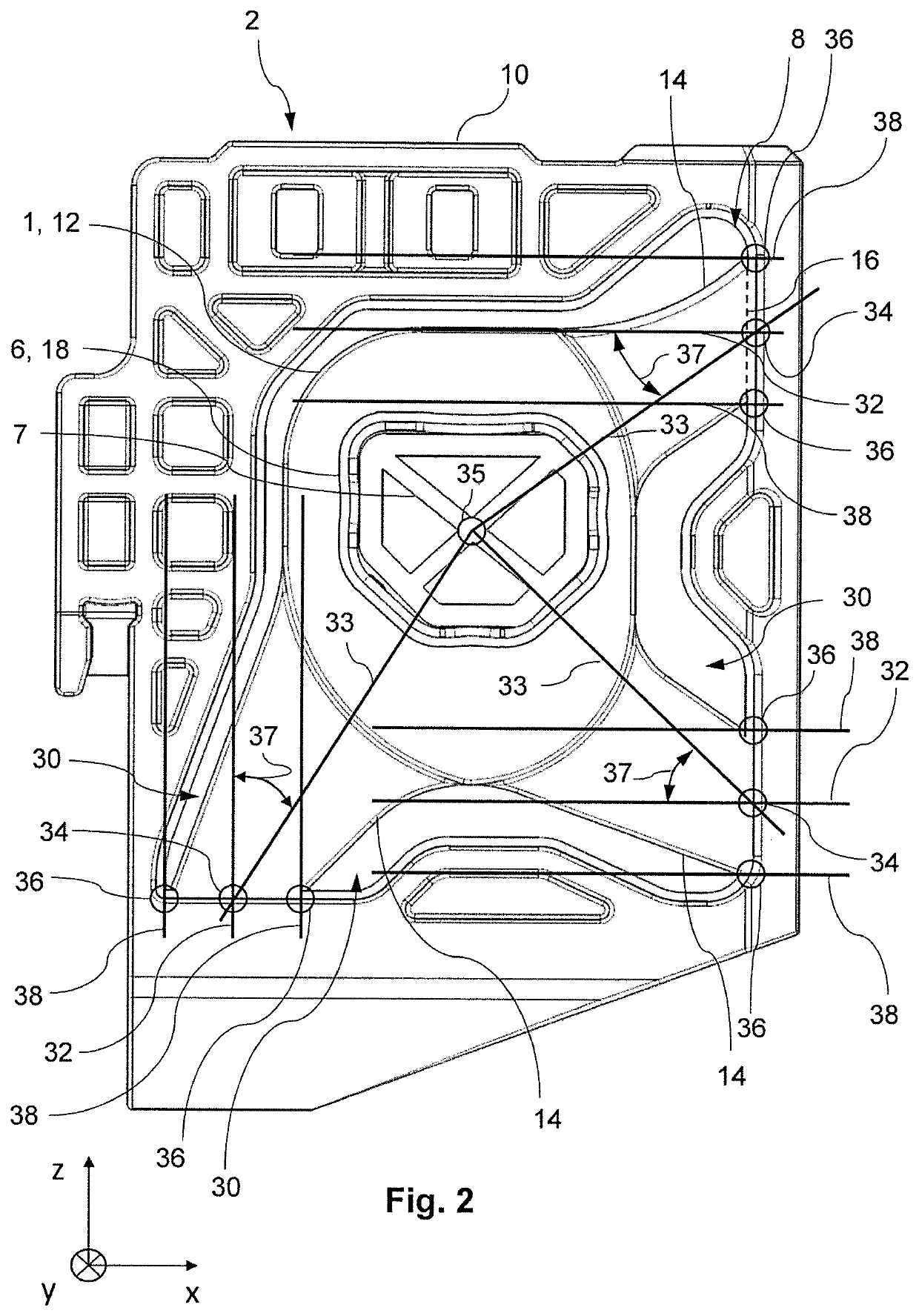
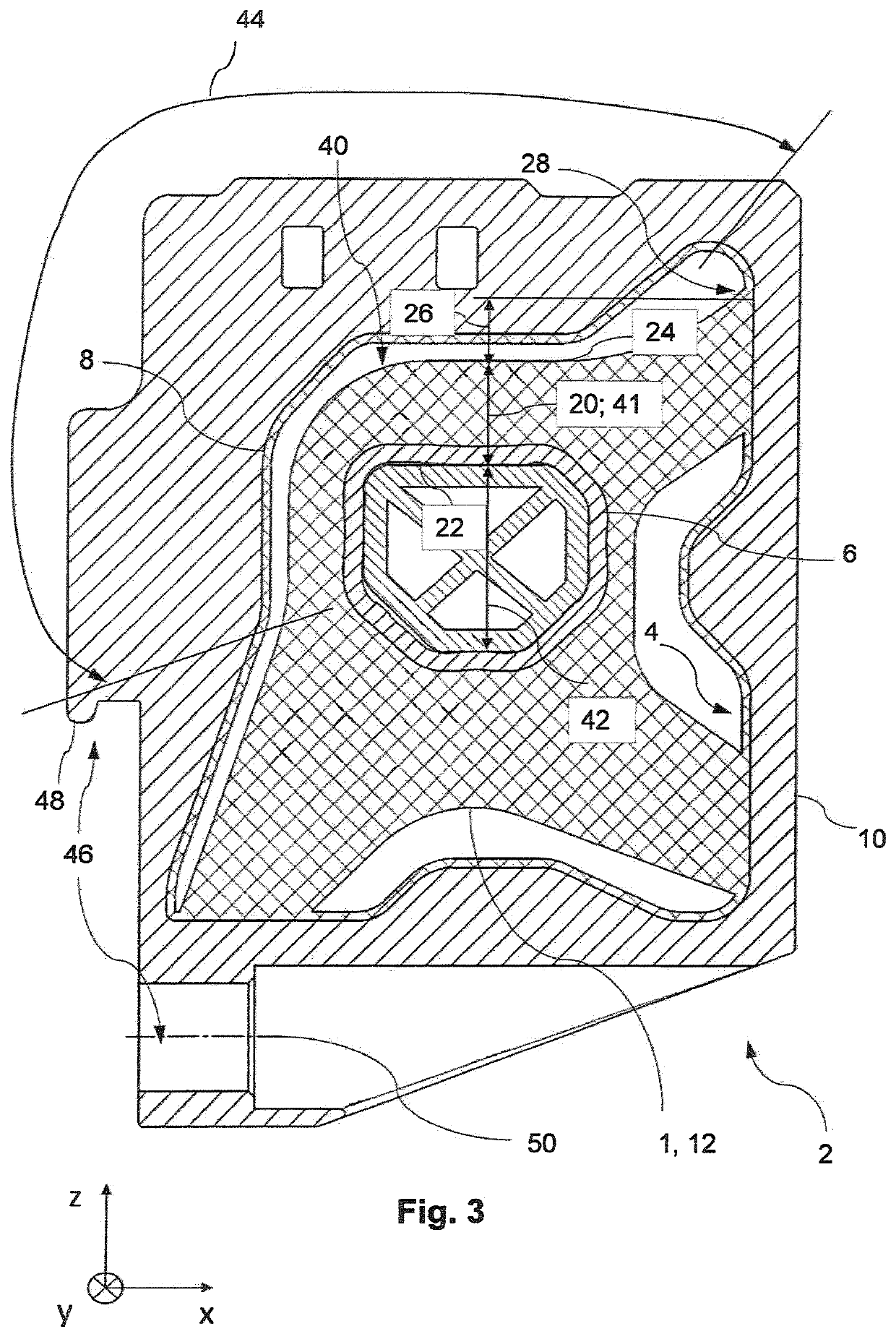
[0064]With reference to FIGS. 1 to 3, an embodiment of an inventive bearing element 1 in a bearing 2 of the present invention is described below, wherein the embodiment shows a bearing 2 for a cooling module of a motor vehicle. In relation to the direction of gravity, the bearing 2 is shown in the installed position. The coordinate system shown in the Figures corresponds to the previously described x-y-z coordinate system.

[0065]In the view shown in FIG. 1, a bearing element 1 of an embodiment is taken up in an inventive bearing 2, especially in a bearing receptacle 4 of the bearing 2.

[0066]The bearing element 1 has an inner connection 6, by means of which a bearing pin 7 of the (not shown) cooling module can be connected. An outer connection 8, by means of which the bearing element 1 with a bearing frame 10 is connectable, can be connected to the inner connection 6. The bearing element 1 comprises an elastomeric element 12.

[0067]As shown here, the outer connection 8 may, for example...


PUM

PropertyMeasurementUnit
pressureaaaaaaaaaa
angleaaaaaaaaaa
angleaaaaaaaaaa

Abstract

A bearing element (1) for mounting a component, especially a cooling module, with an elastomeric element (12), the elastomeric element (12) having an inner connection (6) for connecting to a bearing pin (7) of the component to be mounted, an outer connection (8) for connecting to a bearing frame (10), and at least one support arm (14), which extends between the inner connection (6) and outer connection (8) and elastically connects these together, with a force transfer surface (16) of the outer connection (8) to the bearing frame (10) formed by an outer end face of the support arm (10), and the bearing element (1) formed such that, in the event of an elastic displacement of the inner connection (6) relative to the outer connection (8) in a predetermined, radial displacement direction relative to the bearing element (1) the support arm (14) is stressed predominantly by thrust.

Description

BACKGROUND OF THE INVENTION[0001]The invention relates to a bearing element for the substantially vibration-decoupling mounting of a component, in particular a cooling module, for example for a motor vehicle.[0002]For such bearing elements, the technical challenge consists, on the one hand, of decoupling a component, which is to be mounted therewith, essentially from vibrations, which develop, for example, during the operation of a vehicle and, on the other, to provide a bearing, which is stable enough to take up partly high forces, which act on the bearing or transfer them to a different component, without themselves suffering damage.[0003]Especially in the case of a bearing element for cooling modules of motor vehicles, high forces can occur at the bearing element, for example, in the case of an intermediate cooler, which is integrated in a cooling module, or an intercooler for a turbocharger. For example, at a charging pressure of about 3.5 bar, a force of about 800-850 N can act...

Claims


Application Information

Patent Timeline
Patent Type & Authority Patents(United States)
IPC IPC(8): F16F15/08F16F1/38F16F1/44F16F1/377F16F1/52
CPCF16F1/377F16F1/3835F16F1/52F16F1/44F16F1/3863F16F15/08F16F2236/103F16F2236/12F16F2224/025F16F2236/06F16F1/36F16F1/373F16M13/02
Inventor IRAKI, YOUSSEFGROMES, MARTIN
Owner SUMITOMO RIKO CO LTD
Learn More