
Illumination portion for illuminating a roof opening portion of a vehicle

Active Publication Date: 2020-04-21
KASAI KOGYO CO LTD
View PDF18 Cites 3 Cited by
  • Summary
  • Abstract
  • Description
  • Claims
  • Application Information

AI Technical Summary

Benefits of technology

[0007]The present invention has been made in view of the problems described above, and an object thereof is to provide an illumination structure which provides the structure of the roof opening of a vehicle with a sophisticated enhanced appearance, and with which light incident on a sunshade or a glass roof reflects clearly.
[0016]The present invention provides an illumination structure which provides the structure of the roof opening of a vehicle with a sophisticated enhanced appearance, and with which light incident on the sunshade or the glass roof reflects clearly.

Problems solved by technology

Further, when the sunshade is open, light diffusing inside any vehicle structure, such as the lower surface of the sunshade or the upper surface of the garnish existing around the illumination structure, may reflect contrary to expectations and seen on the glass roof.

Method used


Image

  • Illumination portion for illuminating a roof opening portion of a vehicle
  • Illumination portion for illuminating a roof opening portion of a vehicle
  • Illumination portion for illuminating a roof opening portion of a vehicle

Examples


embodiment

[0030]In the following, with reference to the drawings, a detailed description will be given of an embodiment for carrying out the present invention (hereinafter referred to as the embodiment). Note that, unless otherwise specified, the cabin side (the ground side, the vehicle bottom side) is the front side, and the roof panel side (the sky side, the vehicle top side) is the back side.

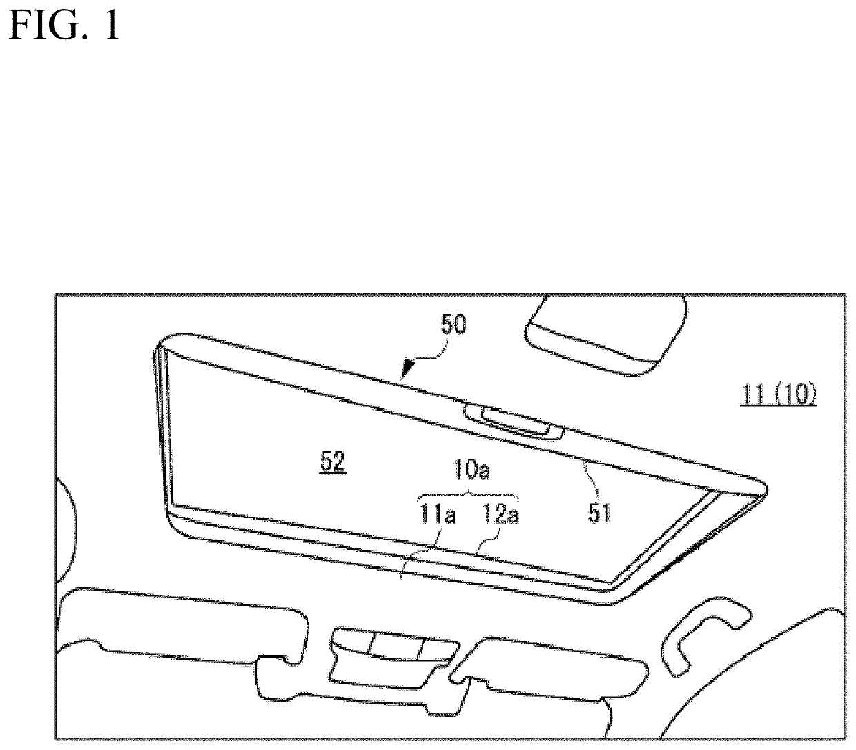
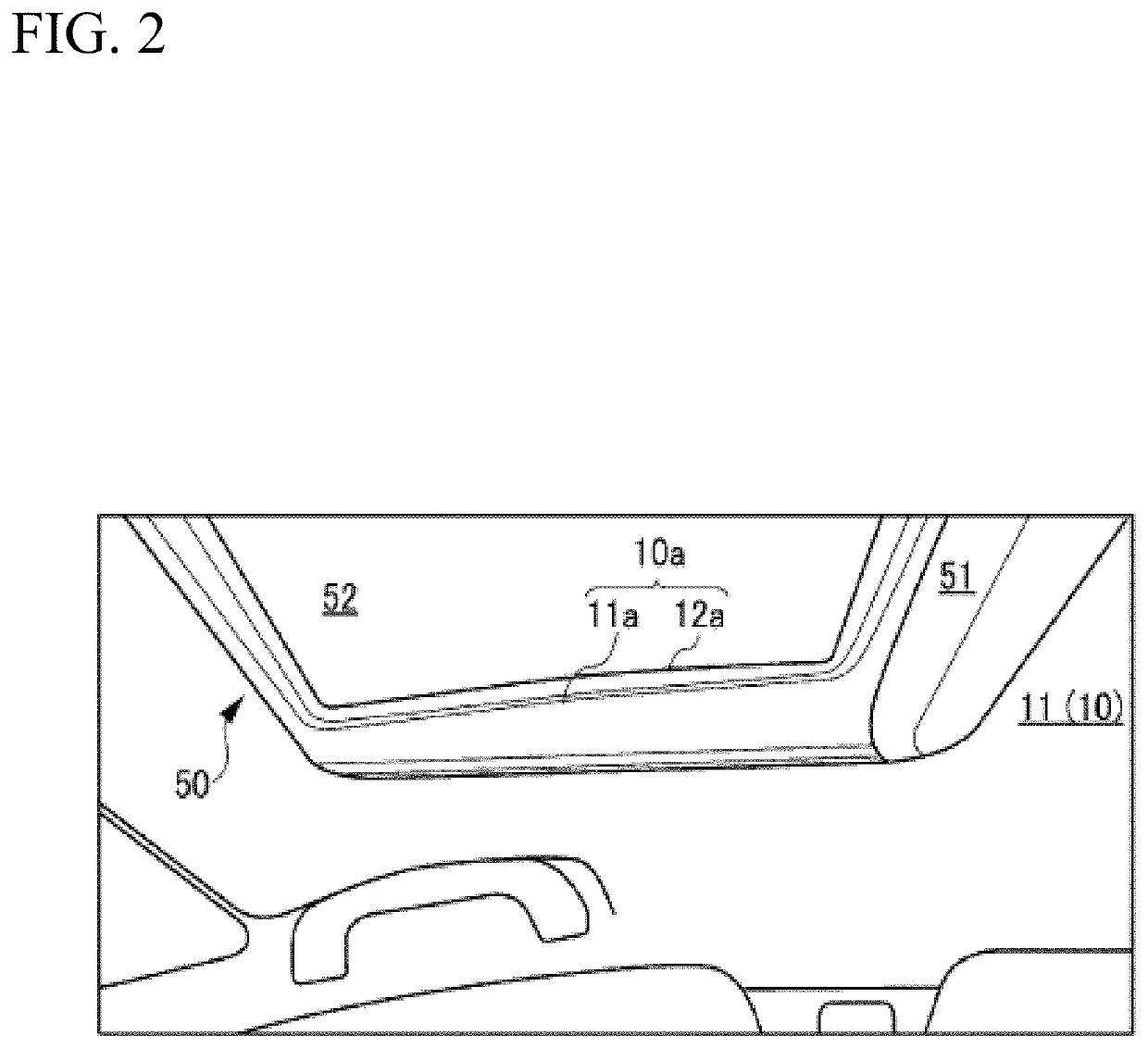
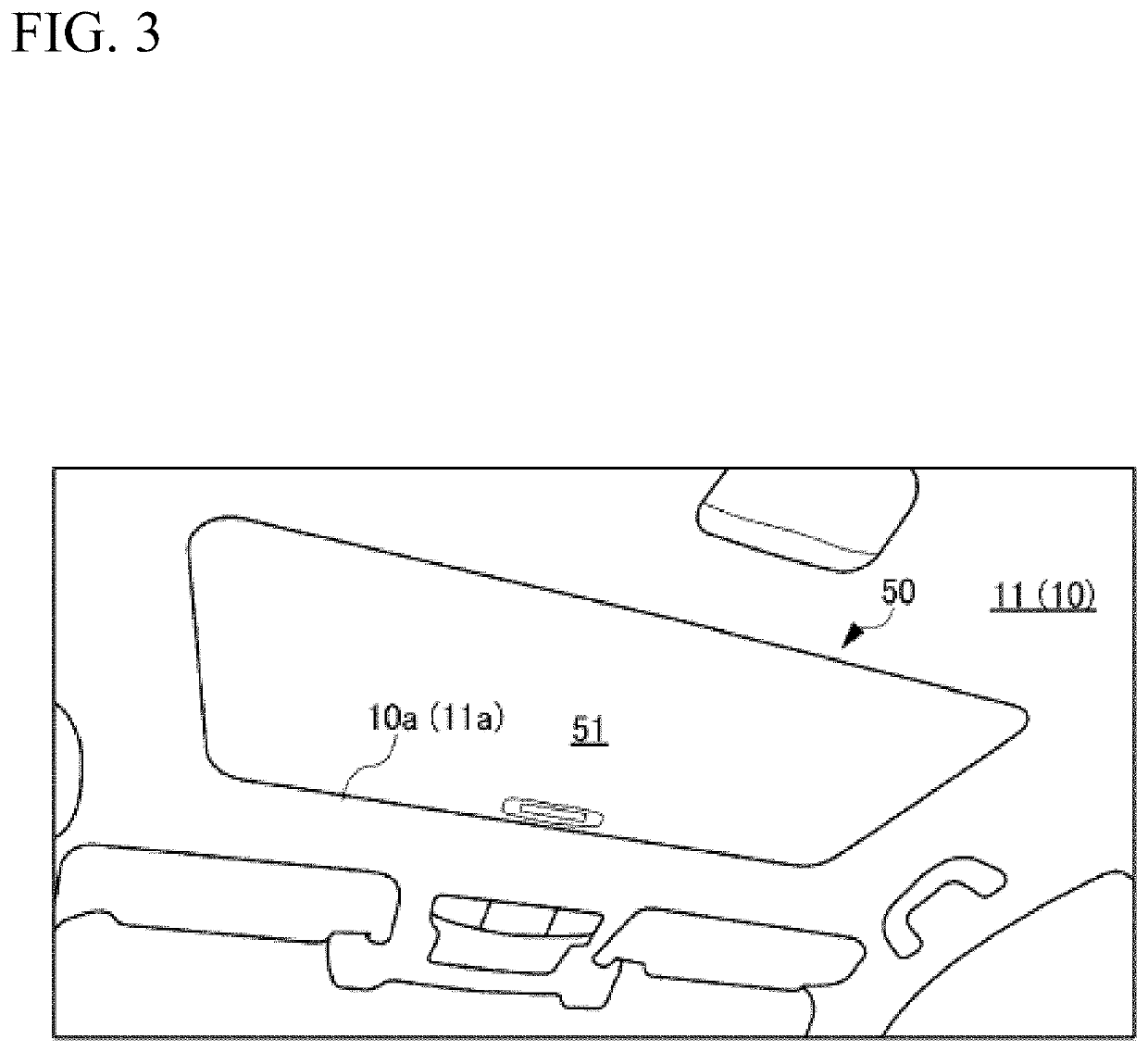
[0031]With reference to FIGS. 1 to 4, a brief description will be given of the structure of a roof 10 (referred to also as the ceiling) of a vehicle in which a sunroof 50 is installed.

[0032]FIG. 1 shows the appearance of a roof opening 10a when a roof 10 is looked up obliquely frontward from the rear side in a vehicle with a sunshade 51 being open in a bright ambient environment. FIG. 2 shows the appearance of the roof opening 10a when the roof 10 is looked up obliquely rightward from the left side in the vehicle with the sunshade 51 being open in a bright ambient environment.

[0033]As shown in FIGS. 1 ...


PUM

PropertyMeasurementUnit
inclination angleaaaaaaaaaa
angleaaaaaaaaaa
structureaaaaaaaaaa

Abstract

An illumination structure of the present invention is an illumination structure that lights a sunshade or a glass roof. The illumination structure includes: a frame-like first bracket coupled to a headliner along the circumferential edge of a headliner opening for reinforcing the headliner opening; a frame-like second bracket coupled to the first bracket so as to be overlaid on the back side of the first bracket for reinforcing the headliner opening in cooperation with the first bracket; and a light emitter held between the first bracket and the second bracket. Light from the light emitter is emitted through a gap between the first bracket and the second bracket.

Description

CROSS-REFERENCE TO RELATED APPLICATIONS[0001]This application is a National Stage Entry application of PCT International Application No. PCT / JP2016 / 082709, filed on Nov. 2, 2016, the entire contents of which are hereby incorporated by reference.BACKGROUND1. Technical Field[0002]The present invention relates to an illumination structure.2. Description of the Background[0003]A conventional illumination structure lighting around the opening at the roof of a vehicle includes a lens provided at a gap between an inner circumferential headliner and an outer circumferential headliner. Light from the lens is diffused inside the cabin through the gap (Japanese Unexamined Patent Application Publication No. 2015-074328 (hereinafter referred to as “Patent Literature 1”)).[0004]While this illumination structure lights the inner circumferential headliner around the roof opening, the illumination structure does not light a sunshade or a glass roof which forms a sunroof provided at the roof opening....

Claims


Application Information

Patent Timeline
Patent Type & Authority Patents(United States)
IPC IPC(8): B60Q3/51B60Q3/64B60J7/043F21V8/00B60Q3/208B60Q3/20G02B1/04
CPCG02B6/001G02B1/045B60Q3/208G02B6/0006B60J7/043B60Q3/64B60Q3/51B60Q3/20G02B1/048C08L33/08G02B1/046
Inventor OSHINA, MASATO
Owner KASAI KOGYO CO LTD
Learn More