Device for measuring femur displacement and method of making orthopedic measurements during a surgical procedure to correct a damaged hip
a technology for femur displacement and surgical procedure, applied in the field of devices for measuring femur displacement and making orthopedic measurements during surgical procedure to correct damaged hips, can solve the problems of not having a measurement arm, and not having a linear coordinate system. , to achieve the effect of prolonging the procedure time and prolonging the duration of the procedur
- Summary
- Abstract
- Description
- Claims
- Application Information
AI Technical Summary
Problems solved by technology
Method used
Image
Examples
example ii
)
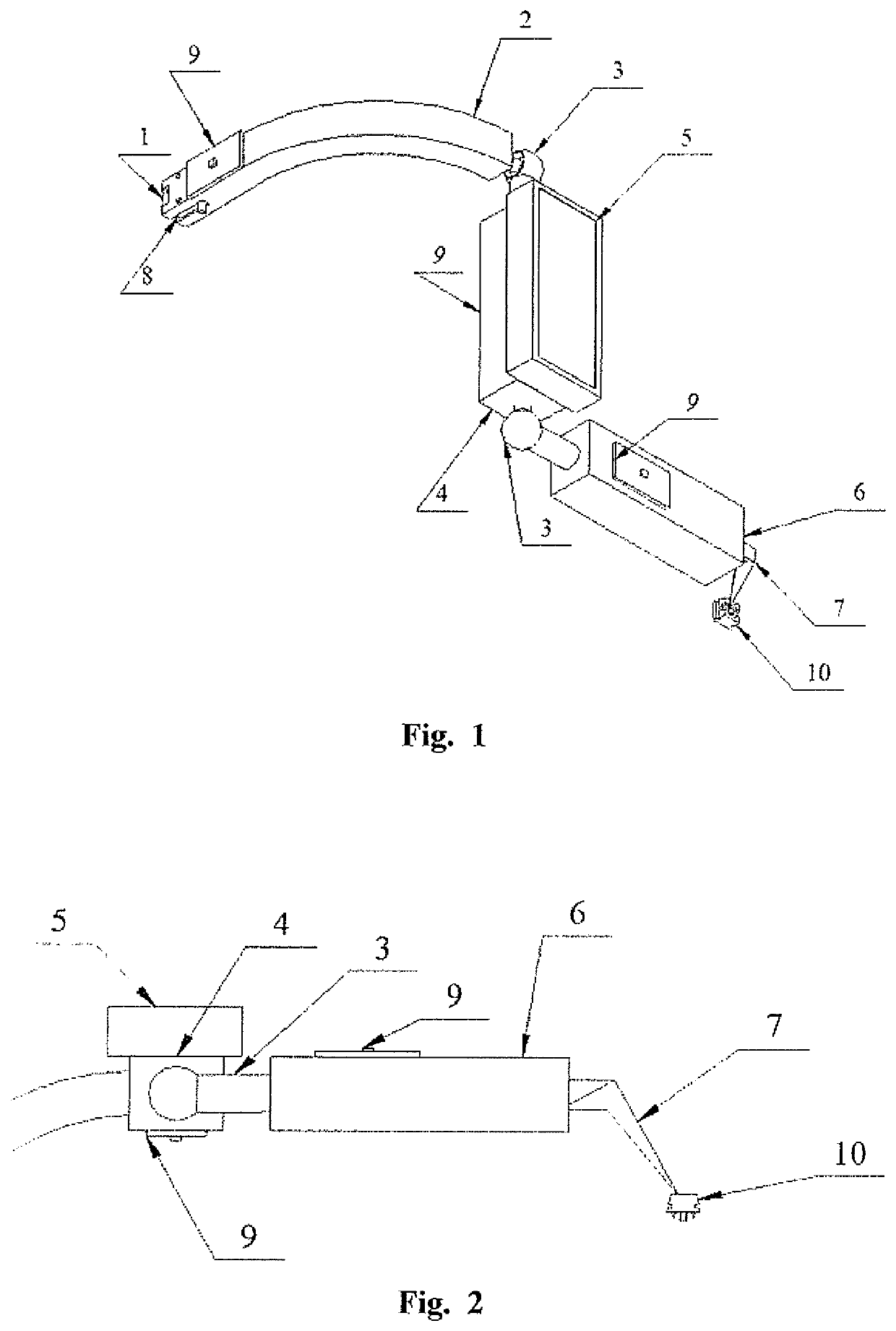
[0039]The device for measuring femur bone displacement during total hip arthroplasty includes base element 1 mounted to the pelvis by means of a screw in a manner preventing it from dislocation during the surgical procedure, marker 10 whose displacement relative to the pelvis is measured and which is mounted to the femur, preferably by means of a screw connection and measurement arm, detachably mounted to base element 1. The measurement arm includes a support mounted to the base element, movable link I-4, movable link II-6 and movable end link III-11 mounted to the marker 10. The form of the marker corresponds to the form of the base element. The links are connected to each other and to the support by means of spherical joints 3. Acceleration sensors, magnetic field sensors and gyroscopic sensors together forming an integrated sensor unit 9 are located on the support and on each link. Microprocessor computing system with a display screen 5 and control buttons is mounted on link I-4...
example iii
/ b>)
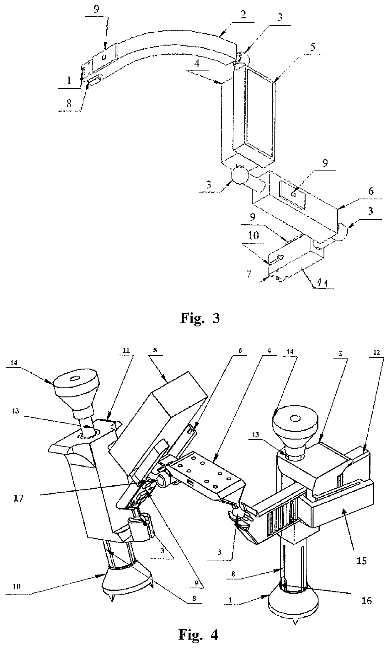
[0040]The device includes: base element 1, lower section of support 2, upper section of support 12, measurement arm link 4, measurement arm link 6 with microprocessor computing system located on it with a display screen 5 and control buttons, movable end link 11, marker 10, as well as four three-axis accelerometers 9 mounted on links 12, 4, 6, 10, respectively.
[0041]Both base 1 and marker 10 take the form of a hollow truncated cone with three sharp spikes protruding downwards and are mounted to the bone by means of a centrally located screw. The measurement arm support includes both lower support 2 and upper support 12 which can linearly move relative to each other after releasing securing lever 15. Lower support 2 is connected with base 1 by means of quickly detachable connection 8 taking the form of an incised sleeve with swellings at the end, inserted into a corresponding socket in base element 1. Rotation of the sleeve relative to base element 1 is blocked by pin 16. After i...
example iv
5 AND 6)
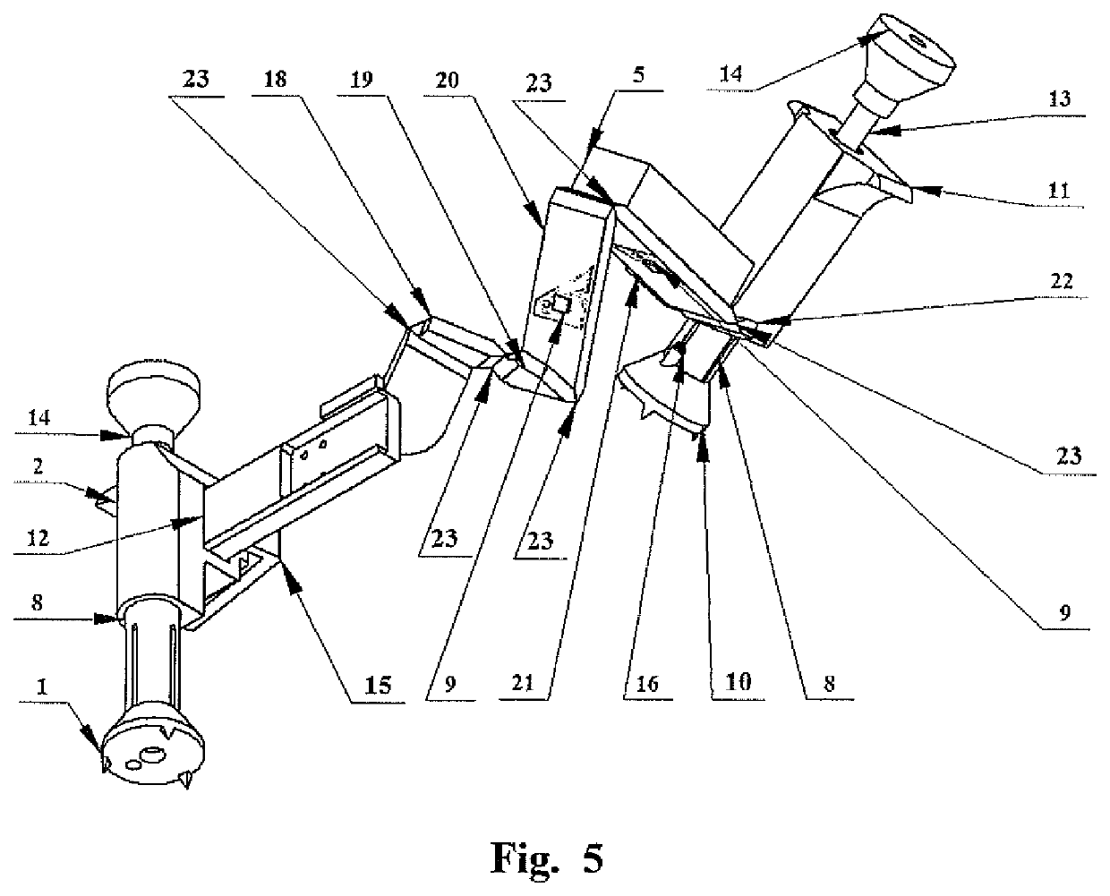
[0043]The device includes: base element 1, lower support 2, upper support 12, movable links 18, 19, 20, 21, 22 of a measurement arm, microprocessor computing system with a display screen 5 and control buttons, movable end link 11, marker 10, as well as seven three-axis accelerometers 9 mounted on links 12, 18, 19, 20, 21, 22, 10, respectively.
[0044]Both base element 1 and marker 10 take the form of a hollow truncated cone with three sharp spikes protruding downwards and are mounted to the bone by means of a centrally located screw. The measurement arm two-piece support includes both lower support 2 and upper support 12 which can linearly move relative to each other after pressing securing lever 15. Lower support 2 is connected with base 1 by means of quickly detachable connection 8 taking the form of an incised sleeve with swellings at the end, inserted into a corresponding socket in base element 1. Rotation of the sleeve relative to base element 1 is blocked by pin 16. Afte...
PUM
 Abstract
Description
Claims
Application Information
 - R&D
- Intellectual Property
- Life Sciences
- Materials
- Tech Scout
- Unparalleled Data Quality
- Higher Quality Content
- 60% Fewer Hallucinations
Browse by: Latest US Patents, China's latest patents, Technical Efficacy Thesaurus, Application Domain, Technology Topic, Popular Technical Reports.
© 2025 PatSnap. All rights reserved.Legal|Privacy policy|Modern Slavery Act Transparency Statement|Sitemap|About US| Contact US: help@patsnap.com


