
Packing

a packing and net-like body technology, applied in the field of packaging, can solve the problems of easy distortion of the shape of the net-like body, difficulty in making the net-like body stand alone, and greatly increased packing manufacturing cost, so as to suppress the deformation and distortion of the packing, reduce the weight of the packing, and suppress the effect of pressure loss

Active Publication Date: 2020-03-24
IHI CORP
View PDF44 Cites 1 Cited by
  • Summary
  • Abstract
  • Description
  • Claims
  • Application Information

AI Technical Summary

Benefits of technology

The technical effect of the patent is to provide a packing for gas-liquid contact that can suppress deformation and distortion while reducing the pressure loss in gas-liquid contact. It achieves this by using a packing with sheet materials arranged in parallel and support members that can prevent deformation and deflection of the sheet materials while securing gas-liquid contact. Additionally, by attaching reinforcing members to the support walls, efficient component transfer and weight reduction of the packing can be realized. The gas-liquid contact apparatus using this packing can provide better gas-liquid contact, efficient component transfer, and good energy efficiency during operation.

Problems solved by technology

However, it takes time and labor to process each of the packing materials disclosed in Publication Documents 1 to 3, and manufacturing cost of the packing is greatly increased.
Particularly, since a net-like body such as wire gauze and a three-dimensional knitted fabric is structurally soft, it is difficult to make the net-like body stand alone, and the shape of the net-like body easily distorts when performing the treatment with the net-like body in a standing state.
Therefore, a support member such as a sheet-like body having strength is required, and therefore the weight of the entire packing increases.
Due to the increase in the weight of the packing, the support structure of the packing needs to be strengthened that leads to an increase in the weight and the size of the apparatus, increasing material costs and manufacturing costs.
In addition, in a structure in which a flow path of a gas flowing in a packing has a complicated shape, the packing hinders the gas flow and pressure loss increases, resulting in lowering of energy efficiency in gas supply.
However, with the structure disclosed in the Publication Document 4, it is difficult to increase the gas-liquid contact area.
Moreover, the absorbent flowing along the packing tends to converge and concentrate locally, and it hardly flows uniformly on the surface of the packing.

Method used


Image

  • Packing
  • Packing
  • Packing

Examples


examples

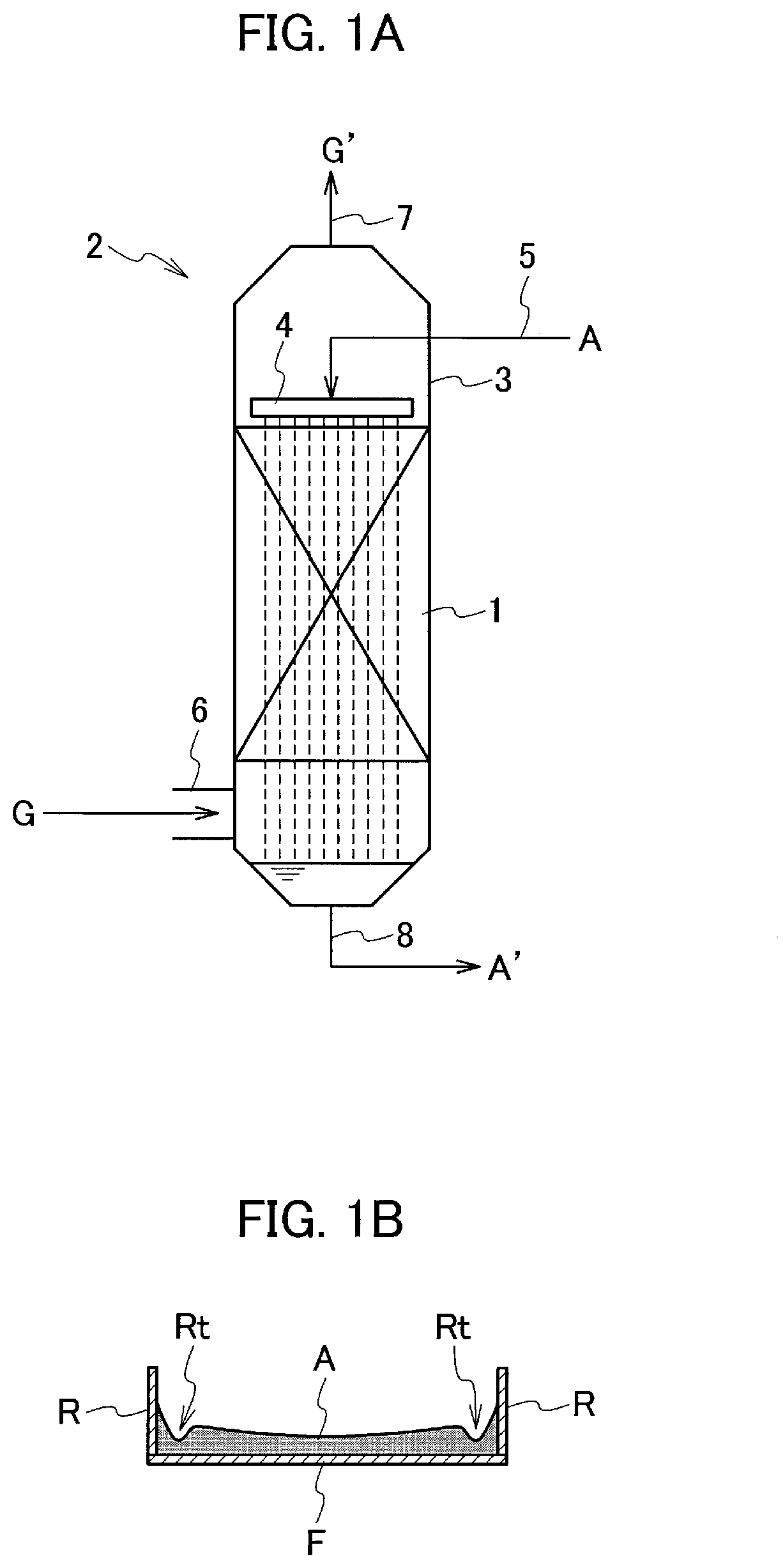
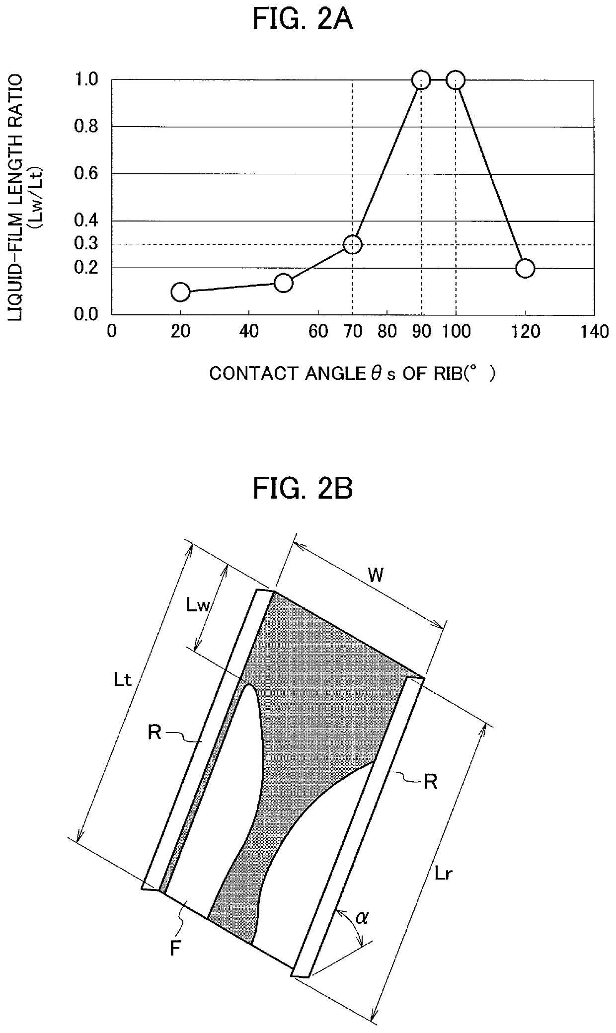
[0074]An analysis of a liquid film flow (CFD analysis) was carried out based on Computational Fluid Dynamics. In this analysis, it is possible to obtain numerical analysis results of three-dimensional unsteady flow by solving a mass conservation equation (equation of continuity) and a momentum conservation equation (Navier-Stokes equation) in a one-fluid model. Note that the analysis was carried out here using FLUENT (registered trademark, ANSYS, Inc.), which is general-purpose thermal fluid analysis software, and the behavior of a gas-liquid interface was predicted by using a VOF (Volume of Fluid) model, which is one of the interface tracking methods. Further, without using the turbulence model, the liquid entrance boundary was specified with the liquid film thickness constant, giving the condition of inflow at uniform flow velocity. The sheet material F and the rib R were subjected to the No-slip condition, and the other boundary surfaces were set to be outflow boundaries of stati...


PUM


Abstract

A packing has a plurality of sheet materials spaced and arranged in parallel, and liquid flows along the flat surface thereof in a standing use state. Each sheet material has at least one member group including a plurality of support members arranged such that the upper end of the uppermost support member corresponds to the upper end of the sheet material and the lower end of the lowermost support member corresponds to the lower end of the sheet material. Each support member has a pair of support walls parallel to the liquid flow direction and perpendicular to the sheet material surface, and a bridging part connecting the support walls. A sandwiching structure is formed that one sheet material is held by at least one support member attached thereto and at least one support member attached to an adjacent sheet material, and it extends linearly through the plurality of sheet materials.

Description

CROSS REFERENCE TO RELATED APPLICATIONS[0001]This application is a continuation application of International Application No. PCT / JP2016 / 077781, filed on Sep. 21, 2016, which claims priority of Japanese Patent Application No. 2015-193399, filed on Sep. 30, 2015, the entire contents of which are incorporated by reference herein.BACKGROUNDTechnical Field[0002]The present disclosure relates to a packing for promoting mass transfer between gas and liquid in gas-liquid contact.Description of the Related Art[0003]Conventionally, a gas separation apparatus employing gas-liquid contact is used in chemical plants, thermal power plants and the like, to separate, remove or recover a specific gas from a gas to be treated, containing various kinds of gases, such as an exhaust gas. For example, in a carbon-dioxide recovering apparatus, a gas containing carbon dioxide gets into contact with an absorbent such as an aqueous monoethanolamine solution, so that carbon dioxide is absorbed and separated. ...

Claims


Application Information

Patent Timeline
Patent Type & Authority Patents(United States)
IPC IPC(8): B01J19/32B01D53/18B01J10/00B01D3/26
CPCB01J10/00B01D53/18B01D3/26B01J19/32B01J2219/32231B01J2219/32213B01J2219/32237B01J2219/32251B01J2219/32262B01J2219/32258B01J2219/32217B01J2219/32206B01J2219/32227
Inventor ISO, YOSHIYUKIHUANG, JIANSAGA, MARIKOMATSUNO, SHINSUKEUCHIDA, HIROYUKIFUJIWARA, NAOKITAKANO, KENJITOKUDA, KENJINAKAMURA, SHIKO
Owner IHI CORP
Learn More