Polarizing film laminate having transparent adhesive layer, and display panel
a technology of adhesive layer and polarizing film, which is applied in the direction of film/foil adhesives, polarising elements, instruments, etc., can solve the problems of poor pattern invisibility, deterioration of properties, and cost of composition itself, so as to reduce the reflection of light and suppress the interface
- Summary
- Abstract
- Description
- Claims
- Application Information
AI Technical Summary
Benefits of technology
Problems solved by technology
Method used
Image
Examples
##ventive example 1
Inventive Example 1
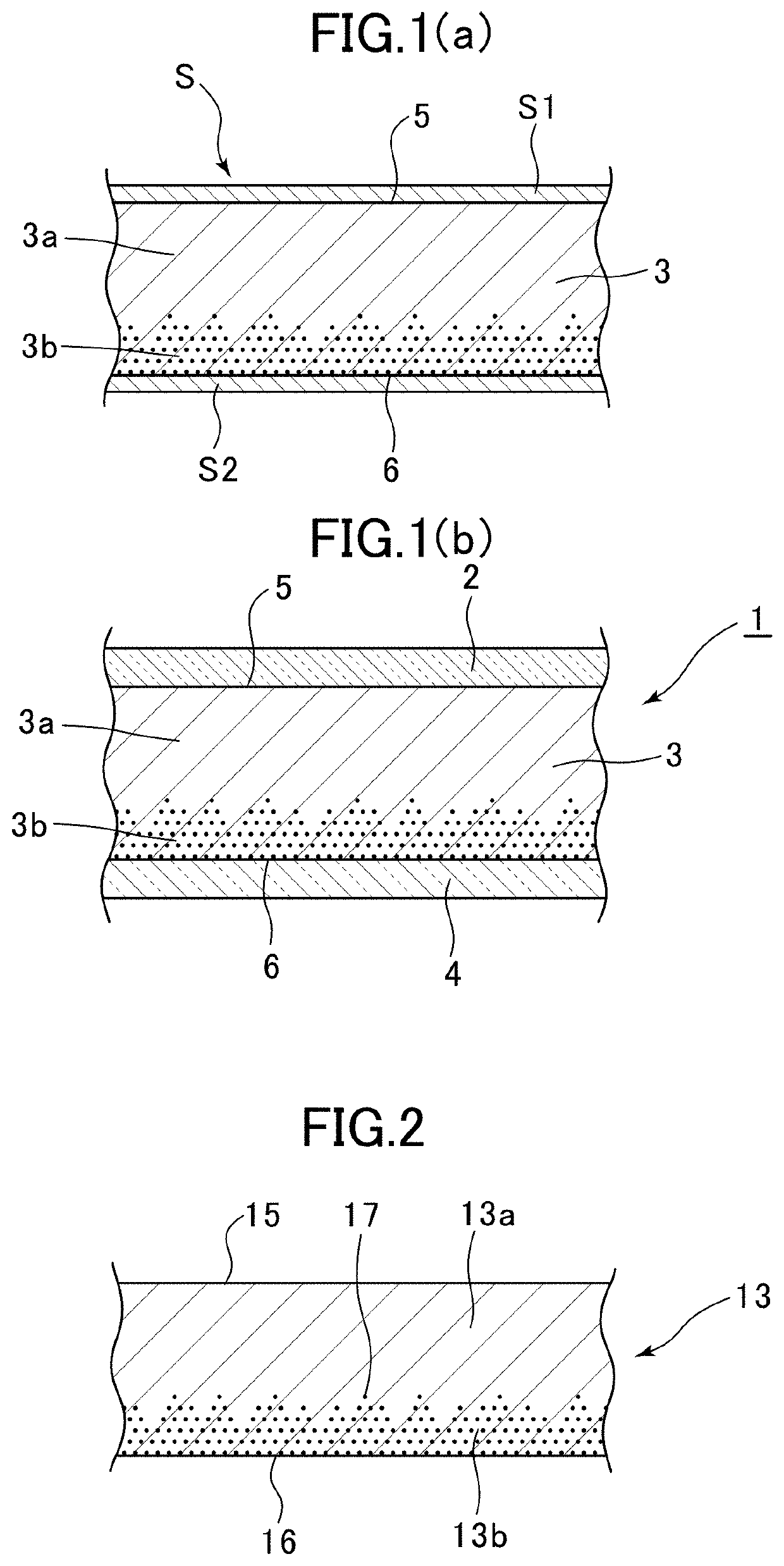
After peeling off the PET separator sheet on the base adhesive zone of the refractive index adjustment zone-formed pressure-sensitive adhesive layer (1), the resulting exposed surface of the refractive index adjustment zone-formed pressure-sensitive adhesive layer (1) was attached to the 20 μm-thick acrylic-based film of the polarizing film (1) to produce a polarizing film laminate (A) to which the refractive index adjustment zone-formed pressure-sensitive adhesive layer (1) was laminated such that the refractive index adjustment zone faced outwardly. After peeling off the PET separator sheet on the refractive index adjustment zone of the produced polarizing film laminate (A), the resulting exposed surface of the polarizing film laminate (A) was attached to the transparent electroconductive layer of the non-patterned transparent electroconductive layer-laminated element substrate (1) in such a manner as to cause the refractive index adjustment zone (zone having th...
##ventive example 2
Inventive Example 2
A film laminate was produced in the same manner as that in Inventive Example 1, except that the pressure-sensitive adhesive and the polarizing film to be laminated were changed to the refractive index adjustment zone-formed pressure-sensitive adhesive layer (2), and the polarizing film (2), wherein, after peeling off the PET separator sheet on the base adhesive zone, the resulting exposed surface was attached to the 20 μm-thick acrylic-based film in such a manner that the refractive index adjustment zone faced outwardly, to thereby produce a polarizing film laminate (B). A laminate configuration of the obtained film laminate in Inventive Example 2 is schematically depicted in FIG. 10(a).
##ventive example 3
Inventive Example 3
A film laminate was produced in the same manner as that in Inventive Example 1, except that the patterned transparent electroconductive layer-laminated element substrate (2) was used as a transparent electroconductive layer supporting substrate. A laminate configuration of the obtained film laminate in Inventive Example 3 is schematically depicted in FIG. 11(a).
PUM
| Property | Measurement | Unit |
|---|---|---|
| thickness | aaaaa | aaaaa |
| refractive index | aaaaa | aaaaa |
| particle size | aaaaa | aaaaa |
Abstract
Description
Claims
Application Information
 - R&D
- Intellectual Property
- Life Sciences
- Materials
- Tech Scout
- Unparalleled Data Quality
- Higher Quality Content
- 60% Fewer Hallucinations
Browse by: Latest US Patents, China's latest patents, Technical Efficacy Thesaurus, Application Domain, Technology Topic, Popular Technical Reports.
© 2025 PatSnap. All rights reserved.Legal|Privacy policy|Modern Slavery Act Transparency Statement|Sitemap|About US| Contact US: help@patsnap.com


