
Apparatus for manufacturing laminated iron core

a technology of laminated iron and manufacturing apparatus, which is applied in the manufacture of dynamo-electric machines, electrical apparatus, and dynamo-electric machines, etc., can solve the problems of difficult work, uneconomical new spacers, etc., and achieves economic manufacturing, reduced productivity, and high workability.

Active Publication Date: 2020-02-11
MITSUI HIGH TEC INC
View PDF12 Cites 0 Cited by
  • Summary
  • Abstract
  • Description
  • Claims
  • Application Information

AI Technical Summary

Benefits of technology

This configuration allows for efficient and safe resin injection into laminated iron cores of different heights using a common die unit, reducing the need for custom spacers and improving worker safety by avoiding direct contact with the apparatus during cooling.

Problems solved by technology

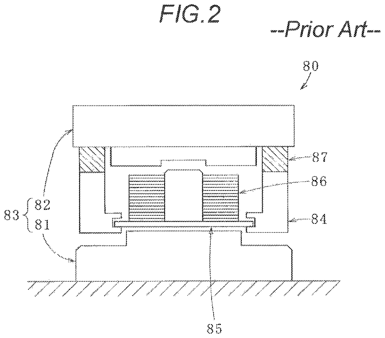
Since the inside space of the manufacturing apparatus is small, it is difficult to do work at the time of replacing the spacer (a hand may be put in a gap of the manufacturing apparatus to do work).
Further, in the case of manufacturing the laminated iron core with a lamination height different from a normal lamination height, for example, a prototype, it is necessary to make a new spacer which is not economical.

Method used


Image

  • Apparatus for manufacturing laminated iron core
  • Apparatus for manufacturing laminated iron core
  • Apparatus for manufacturing laminated iron core

Examples


Embodiment Construction

[0025]Subsequently, an embodiment embodying the aspect of the present invention will be described with reference to the accompanying drawings, and the essence of the present invention will be understood.

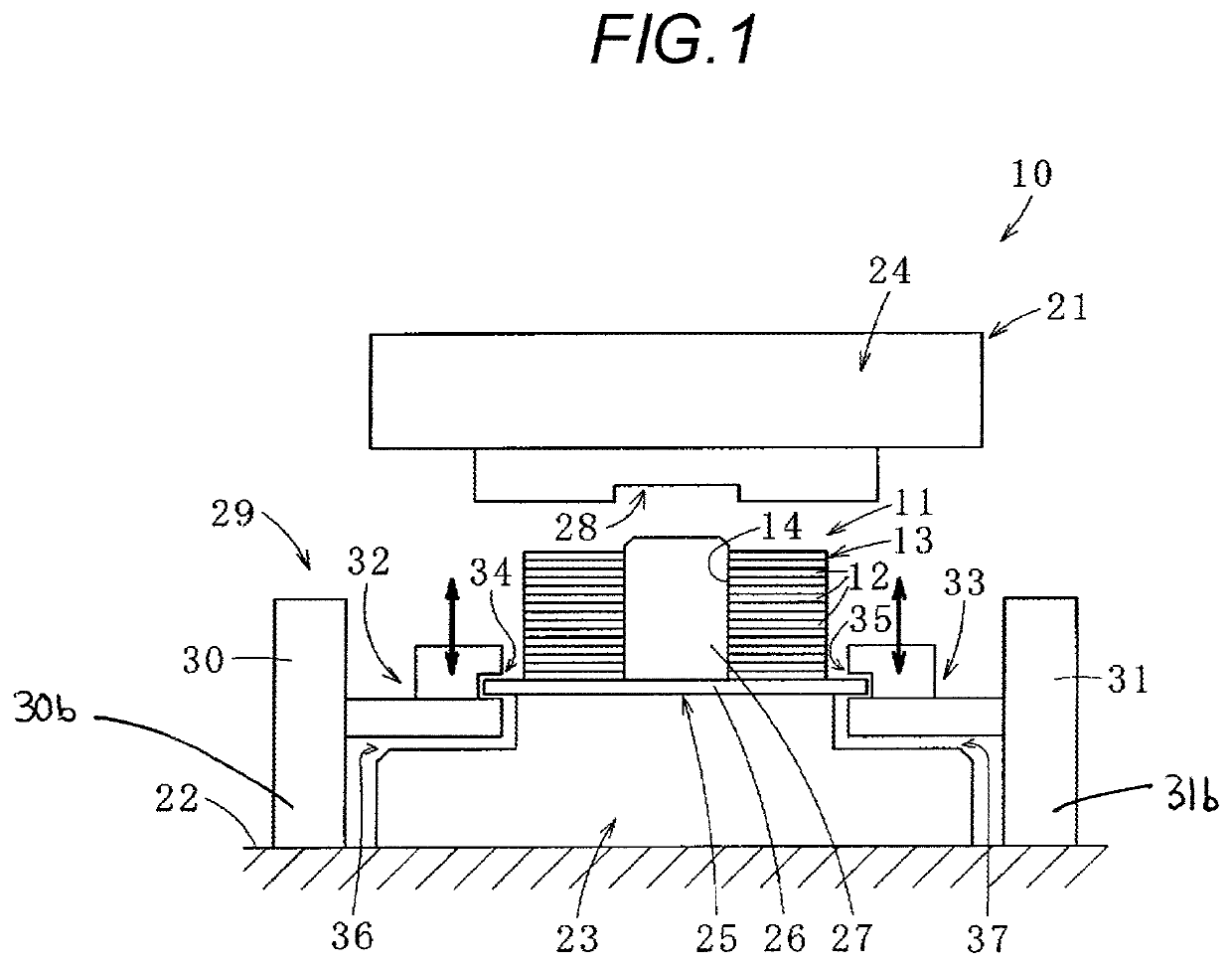
[0026]First, a laminated iron core 11 manufactured using an apparatus 10 for manufacturing the laminated iron core according to one embodiment of the present invention will be described with reference to FIG. 1.

[0027]The laminated iron core 11 is a rotor iron core (rotor).

[0028]This laminated iron core 11 has a laminated iron core body 13 constructed by laminating a plurality of annular (or predetermined shaped) iron core pieces 12. In addition, the laminated iron core body 13 can be constructed by sequentially rotating and laminating plural block iron cores formed by laminating the plural annular iron core pieces 12.

[0029]This iron core piece 12 has an annular integral structure. In addition, the iron core piece may have a divided structure capable of annularly joining plural circul...


PUM

PropertyMeasurementUnit
thicknessaaaaaaaaaa
shapeaaaaaaaaaa
widthaaaaaaaaaa

Abstract

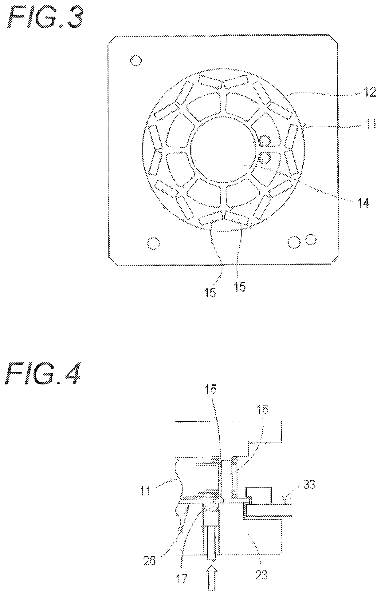
An apparatus for manufacturing a laminated iron core includes a conveyance jig on which a laminated iron core body is placed, a die unit including a lower die and an upper die upwardly and downwardly movable with respect to the lower die, which holds the laminated iron core body placed on the conveyance jig from both sides in a lamination direction of the laminated iron core body between the lower die and the upper die, an injector injecting a resin into a through hole formed through the laminated iron core body held by the die unit from the lower die through the conveyance jig or the upper die, and an upward and downward movement unit capable of upwardly and downwardly moving the conveyance jig with respect to the lower die, and being provided independently from the die unit.

Description

CROSS REFERENCE TO RELATED APPLICATION(S)[0001]This application is based upon and claims the benefit of priority of Japanese Patent Application No. 2015-160417 filed on Aug. 17, 2015, the contents of which are incorporated herein by reference in its entirety.BACKGROUND OF THE INVENTION1. Field of the Invention[0002]The present invention relates to an apparatus for manufacturing a laminated iron core, in which a resin is injected into a through hole of a laminated iron core body in which a plurality of iron core pieces are laminated.2. Description of the Related Art[0003]For example, JP-A-2013-215058 as Patent Reference 1 discloses an apparatus for manufacturing a laminated iron core, in which a permanent magnet inserted into a magnet-insert hole of a laminated iron core body is fixed by a resin.[0004]Concretely, as shown in FIG. 2, an apparatus 80 for manufacturing a laminated iron core includes a die unit 83 having a lower die 81 for injecting a resin and an upwardly and downwardly...

Claims


Application Information

Patent Timeline
Patent Type & Authority Patents(United States)
IPC IPC(8): H02K15/00H02K15/03H01F41/02
CPCH01F41/0233H02K15/03Y10T29/53143H02K15/02Y10T29/49009
Inventor MABU, HIROTOSHISASAKI, HIDEMI
Owner MITSUI HIGH TEC INC
Learn More