
Rotational mechanical thrombectomy device

a mechanical thrombosis and rotating technology, applied in the field of mechanical thrombosis devices, can solve the problems of reducing affecting the quality of life of many individuals, and vte is a significant risk, so as to facilitate the operation

Active Publication Date: 2020-02-11
TELEFLEX MEDICAL INC
View PDF23 Cites 1 Cited by
  • Summary
  • Abstract
  • Description
  • Claims
  • Application Information

AI Technical Summary

Benefits of technology

Effectively treats thrombosis in large veins by directly contacting and breaking down clots, reducing the need for thrombolytic agents and improving patient comfort and mobility, while being easier to use and less burdensome for hospital staff.

Problems solved by technology

VTE is a significant risk in surgical patient populations where preoperative, operative, and postoperative immobilization may lead to blood stasis.
VTE, when poorly treated, may lead to the development of post-thrombotic syndrome (PTS), with symptoms including chronic leg pain, swelling, and ulcers.
As a consequence of PTS, many individuals struggle with a reduced quality of life.
However, the efficacy of these methods is disputed.
One deficiency of these methods is the use of thrombolytic agents, which may present a risk of internal bleeding, including the potential for an intracranial bleeding event.
However, their use can cause bleeding complications.
The use of methods involving thrombolytic agents may also be ineffective to treat against blood clots in larger veins, such as veins located in a patient's leg.
Many thrombolytic agents are also costly, and logistically complicated to use.
But such devices include their own drawbacks.
Oftentimes, these kinds of devices are bulky and may impose a considerable burden on hospital staff.
Patients are also less inclined to ambulate while using these devices because they typically are burdensome to remove and reapply.
Many patients also dislike using mechanical compression systems because such devices are typically uncomfortable.
In addition, these kinds of compression devices also may not be effective at treating thrombosis in larger veins.

Method used


Image

  • Rotational mechanical thrombectomy device
  • Rotational mechanical thrombectomy device
  • Rotational mechanical thrombectomy device

Examples


Embodiment Construction

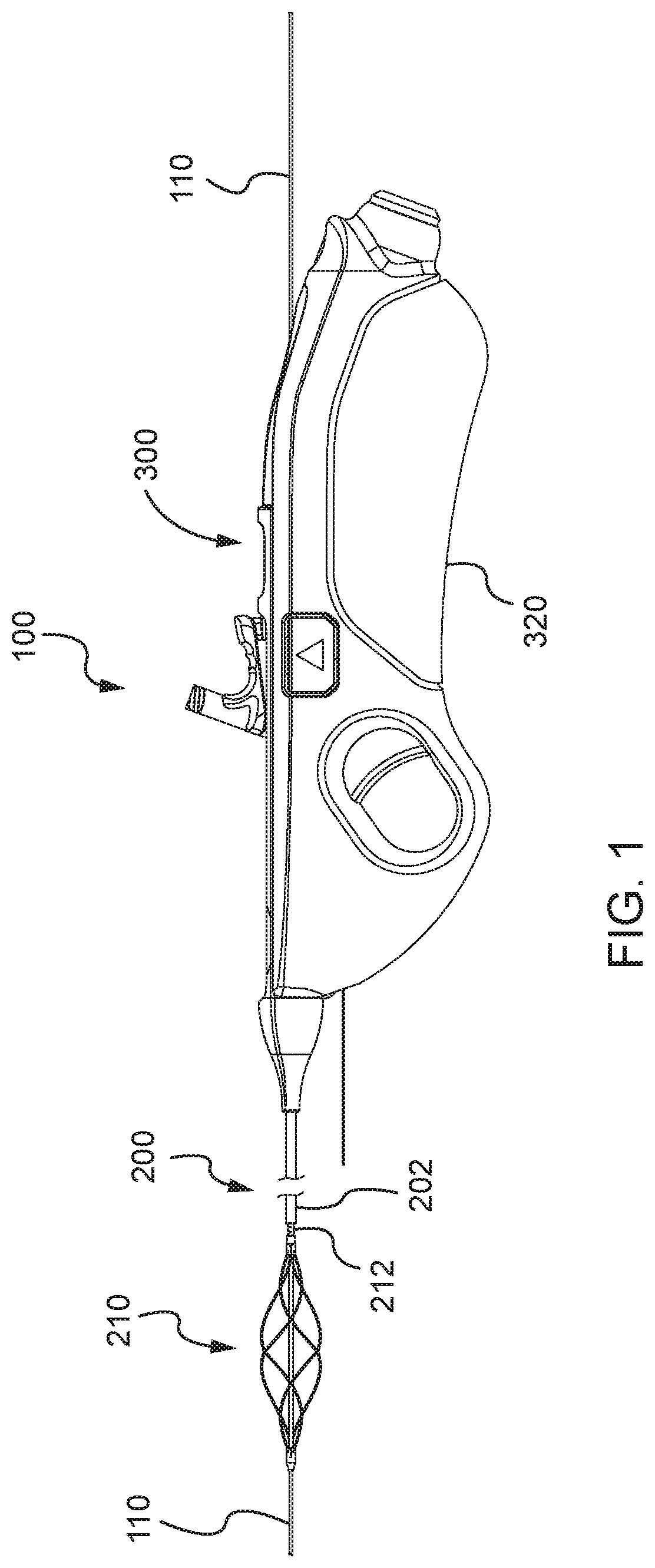
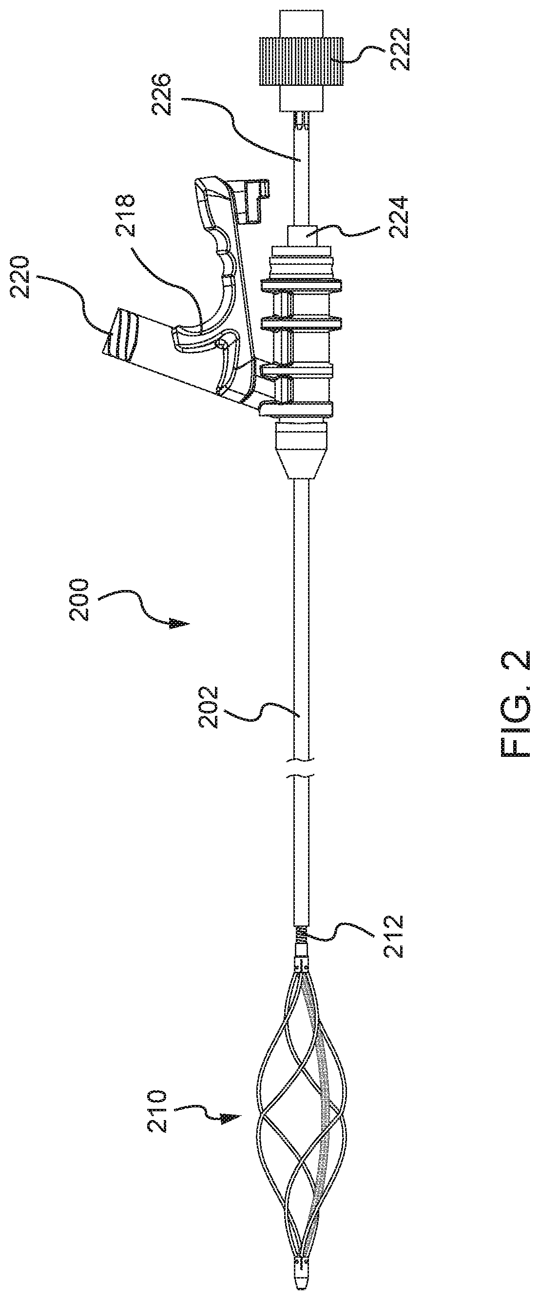
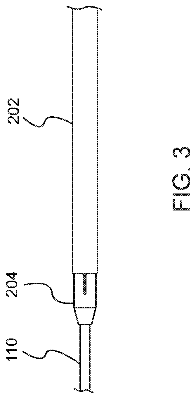
[0038]Systems and methods disclosed herein provide a mechanical thrombectomy device designed to treat deep vein thrombosis. The mechanical thrombectomy device may be designed to effectively work in large veins without using lytics. The device may be a single-use, handheld device that is capable of removing wall adherent and intraluminal clots via rotary maceration. The device is designed to work over a standard size guidewire and, specifically, includes a flexible metallic center lumen that is capable of sliding over a guidewire. The device also includes wall contact features, including a macerating basket that is designed to directly contact and macerate material forming a blood clot. This wall contact design allows the device to be used without lytics or with a reduced amount of lytics. The device may also include user-friendly features, including a cartridge design that facilitates easy connection and separation of a catheter from a handle assembly, as well as two actuator option...


PUM


Abstract

The present disclosure relates to a mechanical thrombectomy device that includes a catheter assembly with a basket assembly formed of a proximal hub and a distal hub; a flexible tube having a first end attached to the proximal hub and a second end attached to the distal hub; and a plurality of basket wires. The flexible tube may be laser-cut to allow for bending, elongation, and compression. The basket wires each have a first end attached to the proximal hub and a second end attached to the distal hub. The basket wires are disposed around the flexible tube and configured to expand to a preset shape. The basket assembly is attached to a distal end of a rotatable shaft. A drive assembly is configured to rotate the rotatable shaft to rotate the basket assembly. The basket assembly when rotated is configured to macerate a material proximate to the basket assembly.

Description

RELATED APPLICATIONS[0001]This application claims priority to U.S. Provisional Patent Application No. 62 / 292,452, filed Feb. 8, 2016, the contents of which are hereby incorporated in its entirety by reference.TECHNICAL FIELD[0002]This application relates generally to a mechanical thrombectomy device and, more specifically, to a thrombectomy device that uses a rotating basket assembly to macerate blood clots.BACKGROUND ART[0003]Venous thromboembolism (VTE), including deep vein thrombosis (DVT) and pulmonary embolism (PE), is a common cardiovascular disorder that affects up to 2 million patients in the U.S. each year. VTE is a significant risk in surgical patient populations where preoperative, operative, and postoperative immobilization may lead to blood stasis. VTE, when poorly treated, may lead to the development of post-thrombotic syndrome (PTS), with symptoms including chronic leg pain, swelling, and ulcers. As a consequence of PTS, many individuals struggle with a reduced qualit...

Claims


Application Information

Patent Timeline
Patent Type & Authority Patents(United States)
IPC IPC(8): A61B17/3207A61B17/00
CPCA61B17/320758A61B17/320725A61B2017/00424A61B2017/320733A61B2017/00367A61B2017/0046A61B2017/320775A61B2217/007A61B2017/00734A61B2017/00973A61B17/221
Inventor ROBERTSON, TAYLORROTH, BRIAN K.TREXLER, WADE K.BOHN, RICHARD E.ROWE, DAVIDDENLINGER, RODNEY WILMERSKELTON, EUGENEWRIGHT, ANTHONYBENSON, RONAN
Owner TELEFLEX MEDICAL INC
Learn More