Retinal cellscope apparatus

a retinal cell and apparatus technology, applied in the field of ocular diagnostic imaging devices, can solve the problems of high equipment cost, limited access to fundus photography, and shortage of trained personnel

Active Publication Date: 2020-01-28
RGT UNIV OF CALIFORNIA
View PDF13 Cites 3 Cited by
  • Summary
  • Abstract
  • Description
  • Claims
  • Application Information

AI Technical Summary

Benefits of technology

[0017]The technology described herein provides an apparatus and methods for digital ocular imaging incorporating a mobile device-based retinal camera that leverages the compact size, high-resolution camera, large data storage capacity, and wireless data transfer capabilities of current mobile devices to capture diagnostic retinal images. The device is preferably a modular system with an interchangeable lens arrangement and camera attachment that enables imaging of different regions of the eye, including the retina, the anterior segment, the cornea, as well as other external parts of the eye such as the eyelid and sclera.
[0019]In one embodiment, the camera includes a custom-designed mobile phone attachment that houses optics capable of capturing a retinal field-of-view of approximately 55 degrees. The device allows a completely portable and inexpensive system for retinal imaging that could be used both in a hospital setting as well as for community eye screening.
[0020]The handheld, modular device provides multi-functionality (fluorescein imaging, fluorescence, brightfield (white light), infrared (IR) imaging, near-infrared (NIR) imaging etc.) and multi-region imaging (retinal, corneal, external, etc.) along with the added features of wireless data transmission and portability, and can serve as a substitute for high cost tools (i.e. slit lamps, binocular indirect ophthalmoscopes, funduscopic cameras, fluorescein imaging cameras, etc.) in regions that require low cost, portable, and more-inclusive tools. The individual imaging modalities can function independently or they can be combined as a “toolkit” to include two or more interchangeable imaging tools.
[0024]With the current movement towards electronic medical records (EMRs), the device can serve as an all-inclusive tool to capture and upload ocular images directly to the patients EMR directly from the mobile device without the need for an intermediate computer system. The technology provides a low cost handheld device that can function as a substitute for conventional high cost medical devices, enabling the recording of digital images of the ophthalmic exam by both experts and non-experts and transmitting these images for remote expert evaluation.

Problems solved by technology

Access to fundus photography is often limited by patient morbidity, high equipment cost, and a shortage of trained personnel.
One limitation found in current imaging systems is the bulky and stationary nature of the equipment.
Standard fundus cameras are cumbersome tabletop devices that are not readily mobile due to the fragility, large size and heavy weight of these devices.
Current tabletop fundus cameras also require the patient to be seated upright, which can be difficult for sick and hospitalized patients.
In addition to dimensional constraints, fundus cameras require a power source to supply power to the illumination, imaging screen, and data processing unit.
An additional factor that increases the size and cost of current fundus imaging devices is the use of dedicated camera modules, dedicated computing systems, and dedicated storage systems for the capture, processing, and storage of the acquired fundus images.
Technical limitations also exist in fundus photography with current devices.
Many devices offer limited fields of view due to the increased complexity associated with wider fields.
Although ophthalmologists are trained to use this equipment, the use of a device that produces an inverted image is often difficult to use by the untrained user since it is not intuitive.

Method used


Image

  • Retinal cellscope apparatus
  • Retinal cellscope apparatus
  • Retinal cellscope apparatus

Examples


example 1

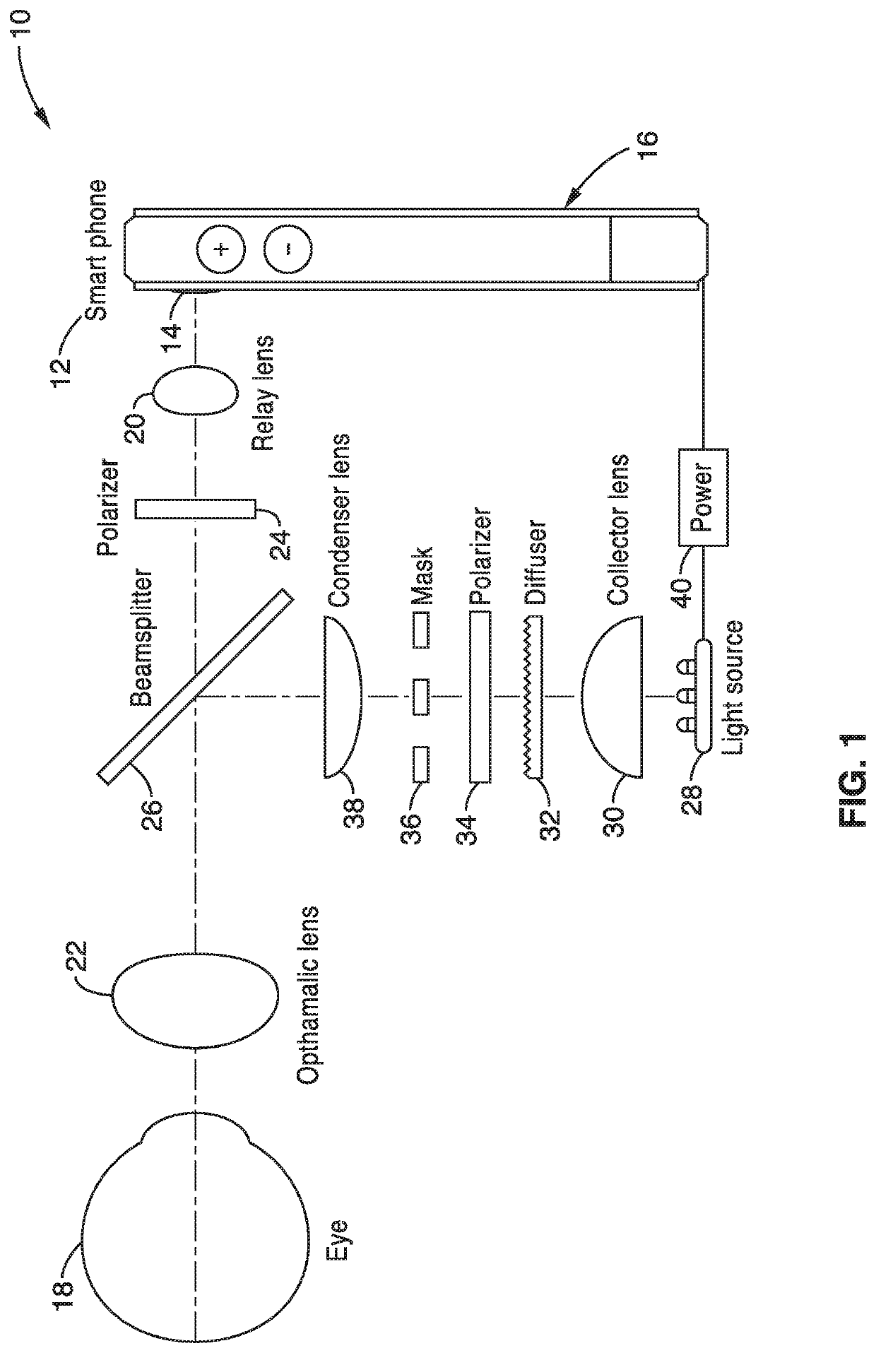
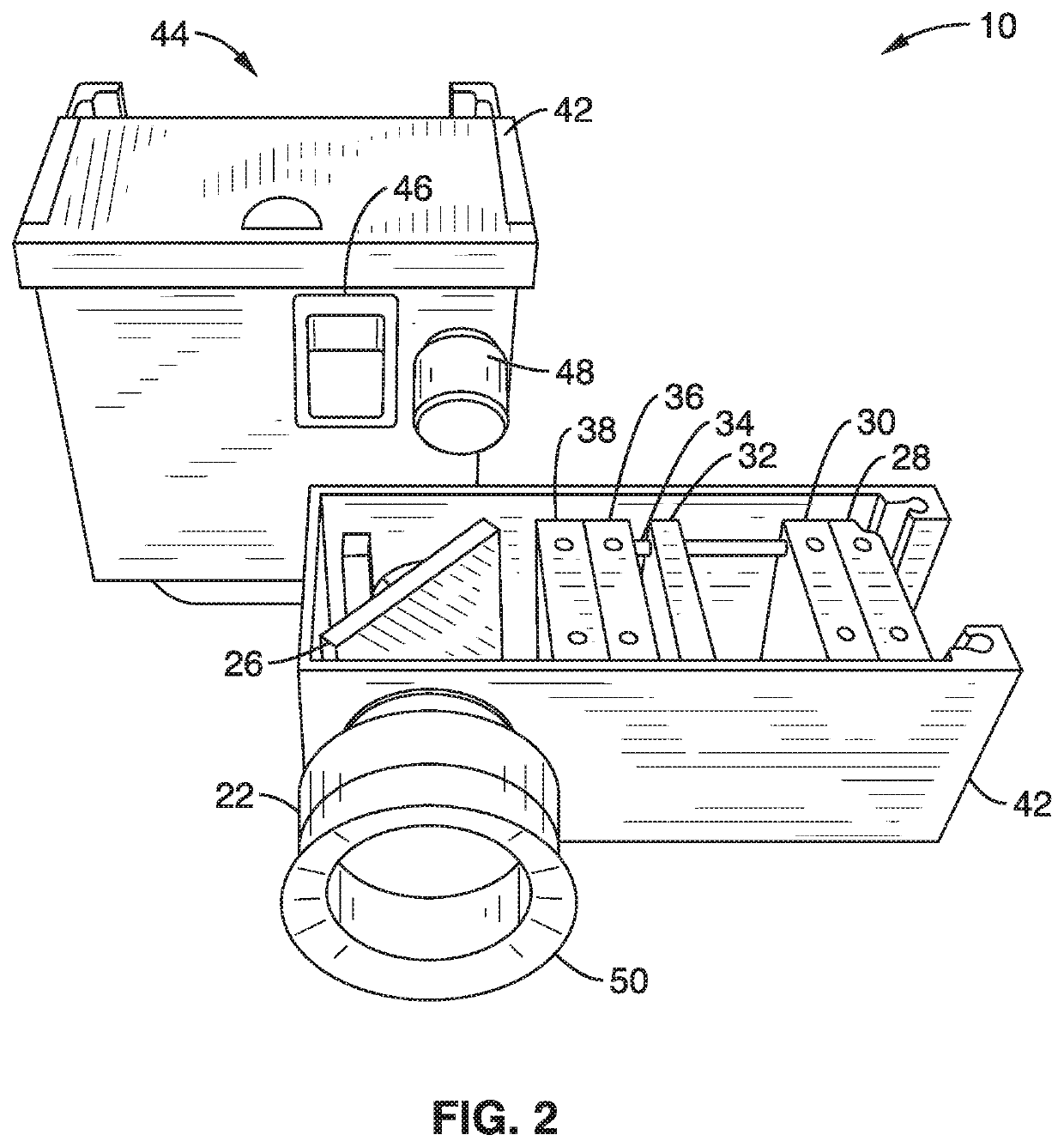
[0105]In order to demonstrate the operational principles of the apparatus and system, a retinal camera apparatus based on a mobile phone was constructed. The camera included a custom-designed mobile phone attachment that housed optics that were capable of capturing a retinal field-of-view of approximately 55 degrees. The device provided wide field imaging, enabling convenient and high-resolution diagnostic imaging for a broad set of applications.

[0106]The housing contained the illumination and collections optics, and an integrated phone holder that ensured alignment of the optics with the camera on the phone. The acrylonitrile butadiene styrene (ABS) plastic housing was designed and constructed for use with an iPhone 4S® mobile phone. The phone required no modification, and the mobile phone could easily slide in and out of the holder. A rubber cup on the lens eye piece rested on the orbital rim of the sitting or supine subject, providing user-controlled stabilization of the apparatu...

example 2

[0111]To assess the potential for the device as a telemedicine tool, diagnostic quality images of diabetic retinopathy and active CMV retinitis were captured from dilated patients in Thailand and transmitted directly from the mobile phone devices to a secure server. These images were of sufficient quality to enable the remote ophthalmologist in the United States to accurately provide a real-time diagnosis of the retinal diseases.

[0112]The mobile phone-based retinal camera apparatus enabled the capture of fundus images remotely. When used through a dilated pupil, the device captures a field-of-view of approximately 55 degrees in a single fundus image. The images were captured on 2652×2448 pixel camera sensor, resulting in approximately 48 pixels per retinal degree. This surpasses the minimum image resolution requirement of 30 pixels per degree suggested by the United Kingdom Nation Health Service for diabetic retinopathy screening.

[0113]Based on initial testing with the device, the t...


PUM


Abstract

A handheld, ocular imaging device and system that employs the camera, processor and programming of a mobile phone, tablet or other smart device coupled to optical elements and illumination elements that can be used to image the structures of the eye in home-based, ambulatory-care, hospital-based, or emergency-care settings, is presented. The modular device provides multi-functionality (fluorescein imaging, fluorescence, brightfield, infrared (IR) imaging, near-infrared (NIR) imaging) and multi-region imaging (retinal, corneal, external, etc.) of the eye along with the added features of image processing, storage and wireless data transmission for remote storage and evaluation. Acquired ocular images can also be transmitted directly from the device to the electronic medical records of a patient without the need for an intermediate computer system.

Description

CROSS-REFERENCE TO RELATED APPLICATIONS[0001]This application is a 35 U.S.C. § 111(a) continuation of PCT international application number PCT / US2014 / 060184 filed on Oct. 10, 2014, incorporated herein by reference in its entirety, which claims priority to, and the benefit of, U.S. provisional patent application Ser. No. 61 / 889,084 filed on Oct. 10, 2013, incorporated herein by reference in its entirety. Priority is claimed to each of the foregoing applications.[0002]The above-referenced PCT international application was published as PCT International Publication No. WO 2015 / 054672 on Apr. 16, 2015, which publication is incorporated herein by reference in its entirety.STATEMENT REGARDING FEDERALLY SPONSORED RESEARCH OR DEVELOPMENT[0003]Not ApplicableINCORPORATION-BY-REFERENCE OF COMPUTER PROGRAM APPENDIX[0004]Not ApplicableBACKGROUND[0005]1. Technical Field[0006]This technology pertains generally to ocular diagnostic imaging devices, and more particularly to a portable handheld smart...

Claims


Application Information

Patent Timeline
Patent Type & Authority Patents(United States)
IPC IPC(8): A61B3/14A61B3/00A61B3/12
CPCA61B3/0091A61B3/12A61B3/0025A61B3/14A61B3/10H04N5/33H04N23/56H04N23/661H04N23/74
Inventor FLETCHER, DANIELMAAMARI, ROBISWITZ, NEILMARGOLIS, TODD P.
Owner RGT UNIV OF CALIFORNIA
Why Eureka
Try Eureka