
Hybrid air-gap / solid-state circuit breaker

a solid-state circuit breaker and hybrid technology, applied in the direction of protective switch operation/release mechanism, protective switch details, polyphase induction motor starter, etc., can solve the problems of slow reaction to faults, conventional circuit breakers, and at least several milliseconds

Active Publication Date: 2020-01-21
ATOM POWER INC
View PDF11 Cites 17 Cited by
  • Summary
  • Abstract
  • Description
  • Claims
  • Application Information

AI Technical Summary

Benefits of technology

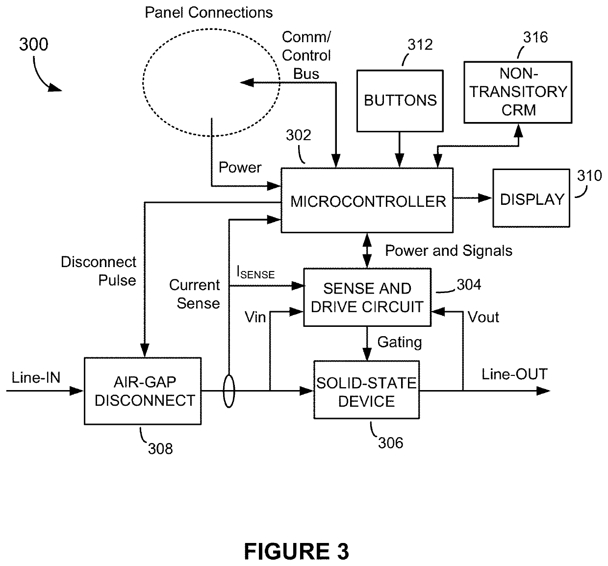
[0009]A hybrid air-gap / solid-state device protection device (PD) for use in an electrical power distribution system is disclosed. The hybrid air-gap / solid-state PD includes an air-gap disconnect unit connected in series with a solid-state device, a sense and drive circuit, and a microcontroller. Upon the sense and drive circuit detecting an impending fault or exceedingly high and unacceptable overvoltage condition in the PD's load circuit, the sense and drive circuit generates a gating signal that quickly switches the solid-state device OFF. Meanwhile, the microcontroller generates a disconnect pulse for the air-gap disconnect unit, which responds by forming an air gap in the load circuit. Together, the switched-OFF solid-state device and air gap protect the load and associated load circuit from being damaged and also serve to electrically and physically isolate the source of the fault or overload condition from the remainder of the electrical power distribution system. The advantage of employing the solid-state device is that impending faults can be reacted to in a matter of microseconds. The air gap formed by the air-gap disconnect unit isolates the fault even if the solid-state device fails to switch OFF or malfunctions, ensuring that the PD complies with electrical codes, regulations and certification requirements.

Problems solved by technology

One significant problem with conventional circuit breakers is that they are slow to react to faults.
Due to their electromechanical construction, conventional circuit breakers will typically require at least several milliseconds to isolate a fault.
The slow reaction time is undesirable since it raises the risk of fire hazards, damage to electrical equipment, and even arc flashes, which can occur when a short circuit or bolted fault is not isolated quickly enough.
Arc flashes are therefore clearly extremely hazardous to life, property and electrical equipment.
In addition to being slow at isolating faults, conventional circuit breakers are highly variable.
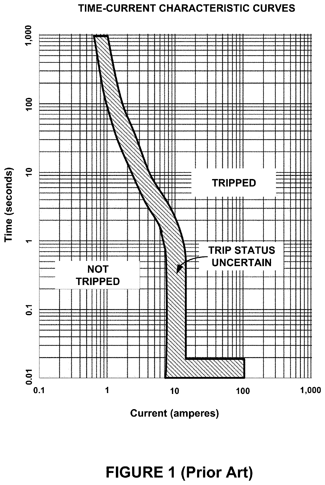
Due to the lack of precision and high degree of variability of conventional circuit breakers, manufacturers will typically provide time-current characteristic data for each type and rating of circuit breaker that they manufacture and sell.
The lack of precision and high degree of variability of conventional circuit breakers make coordination studies difficult to perform.
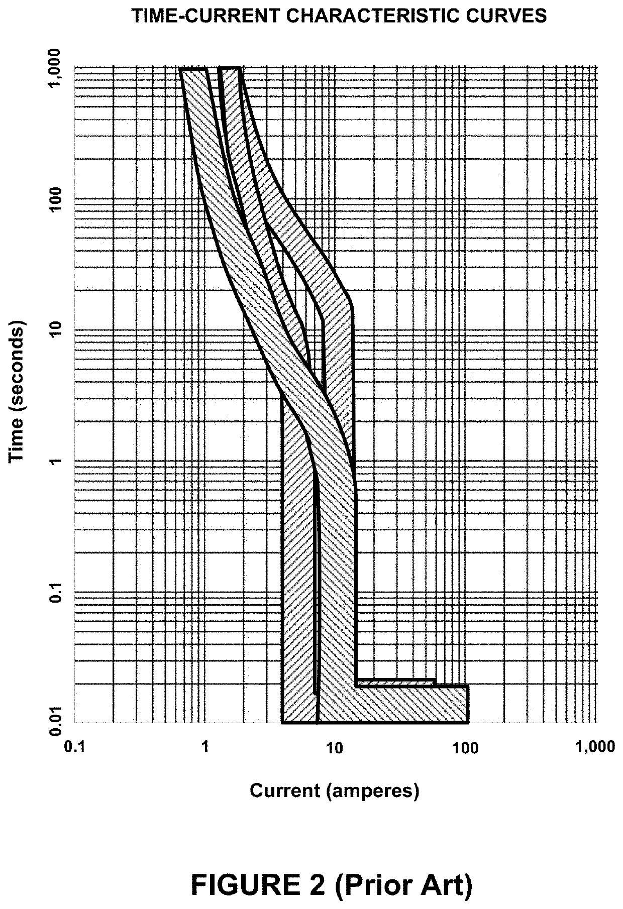
Unfortunately, due to the lack of precision and the resulting uncertainty bands in the time-current characteristics, the coordination study cannot always be completed as required or desired, and the uncertainty bands of the various circuit breakers end up overlapping to some extent, as illustrated in FIG. 2.
The overlapping uncertainty bands is problematic since it results in the possibility that upstream circuit breakers will trip prematurely or unnecessarily in response to an impending fault, instead of by a circuit breaker located further downstream that is closer to the impending fault.
The premature or unnecessary tripping of the upstream circuit breaker is undesirable since it can result in a larger section of the distribution system being de-energized than is necessary.
However, their slow reaction times, lack of precision, and high degree of variability are all undesirable characteristics.
Not only do the slow reaction times result in inadequate protection against the possibility of arc flashes, the high degree of variability and lack of precision make coordination studies difficult, and in some cases even impossible, to perform.

Method used


Image

  • Hybrid air-gap / solid-state circuit breaker
  • Hybrid air-gap / solid-state circuit breaker
  • Hybrid air-gap / solid-state circuit breaker

Examples


Embodiment Construction

[0026]Referring to FIG. 3, there is shown a drawing depicting a hybrid air-gap / solid-state circuit breaker 300 (also referred to as a “protection device” or “PD” in the detailed description below), according to one embodiment of the present invention. The PD 300 comprises a microcontroller 302; a sense and drive circuit 304; a solid-state device 306; and an air-gap disconnect unit 308. The microcontroller 302, sense and drive circuit 304, and other components of the PD 300 are powered by a direct current (DC) power supplied by one or more local DC power supplies independent of the electrical distribution system in which the PD 300 is configured or from an alternating current (AC) to DC power converter that produces DC power from an AC power source in the electrical distribution system. The solid-state device 306 comprises an electrically controlled solid-state device (or device(s)), such as an insulated gate bipolar junction transistor (IGBT), power metal-oxide-semiconductor field e...


PUM


Abstract

A hybrid air-gap / solid-state device protection device (PD) for use in an electrical power distribution system includes an air-gap disconnect unit connected in series with a solid-state device, a sense and drive circuit, and a microcontroller. Upon the sense and drive circuit detecting an impending fault or exceedingly high and unacceptable overvoltage condition in the PD's load circuit, the sense and drive circuit generates a gating signal that quickly switches the solid-state device OFF. Meanwhile, the microcontroller generates a disconnect pulse for the air-gap disconnect unit, which responds by forming an air gap in the load circuit. Together, the switched-OFF solid-state device and air gap protect the load and associated load circuit from being damaged. They also serve to electrically and physically isolate the source of the fault or overload condition from the remainder of the electrical power distribution system.

Description

CROSS-REFERENCE TO RELATED APPLICATIONS[0001]This application claims the benefit of U.S. Provisional Patent Application No. 62 / 301,948, filed Mar. 1, 2016.BACKGROUND OF THE INVENTION[0002]Electrical circuit breakers are used in electrical distribution systems to protect electrical loads and conductors from being exposed to overcurrent conditions. In general, there are two types of overcurrent conditions—an overload and a fault. The National Electrical Code (NEC) defines an overload as: “operation of equipment in excess of normal, full-load rating, or conductor in excess of rated ampacity that when it persists for a sufficient length of time, would cause damage or dangerous overheating.” Faults typically produce much higher overcurrents than do overloads, depending on the fault impedance. A fault with no impedance is referred to as a “short circuit” or as a “bolted fault.”[0003]Conventional circuit breakers are mechanical in nature. They have electrical contacts that are physically s...

Claims


Application Information

Patent Timeline
Patent Type & Authority Patents(United States)
IPC IPC(8): H01H7/08H02H7/08H02H3/20H02H7/22H02H3/38H02H3/08H02H3/42H01H71/12H01H9/54H02H7/085H02P1/26H01H71/10
CPCH02H3/20H02H3/42H02H7/222H02P1/26H02H7/0833H02H3/08H01H71/123H02H7/0855H02H7/0856H01H9/548H02H3/382H01H71/1081H01H9/54H01H33/16H01H89/00H02H3/02H02H3/44H02H7/26
Inventor KENNEDY, RYANKOUROUSSIS, DENIS
Owner ATOM POWER INC
Learn More