Brain mapping system and method thereof

a brain mapping and brain technology, applied in the field of brain mapping system, can solve the problems of limited conventional methods used for acquiring brain activity and inability to monitor in real tim

Active Publication Date: 2019-12-24
CHEN CHIUN FAN
View PDF8 Cites 0 Cited by
  • Summary
  • Abstract
  • Description
  • Claims
  • Application Information

AI Technical Summary

Problems solved by technology

Techniques conventionally used for acquiring brain activity are limited by either their temporal or spatial resolutions and thus are infeasible for real-time monitoring.

Method used


Image

  • Brain mapping system and method thereof
  • Brain mapping system and method thereof
  • Brain mapping system and method thereof

Examples


Embodiment Construction

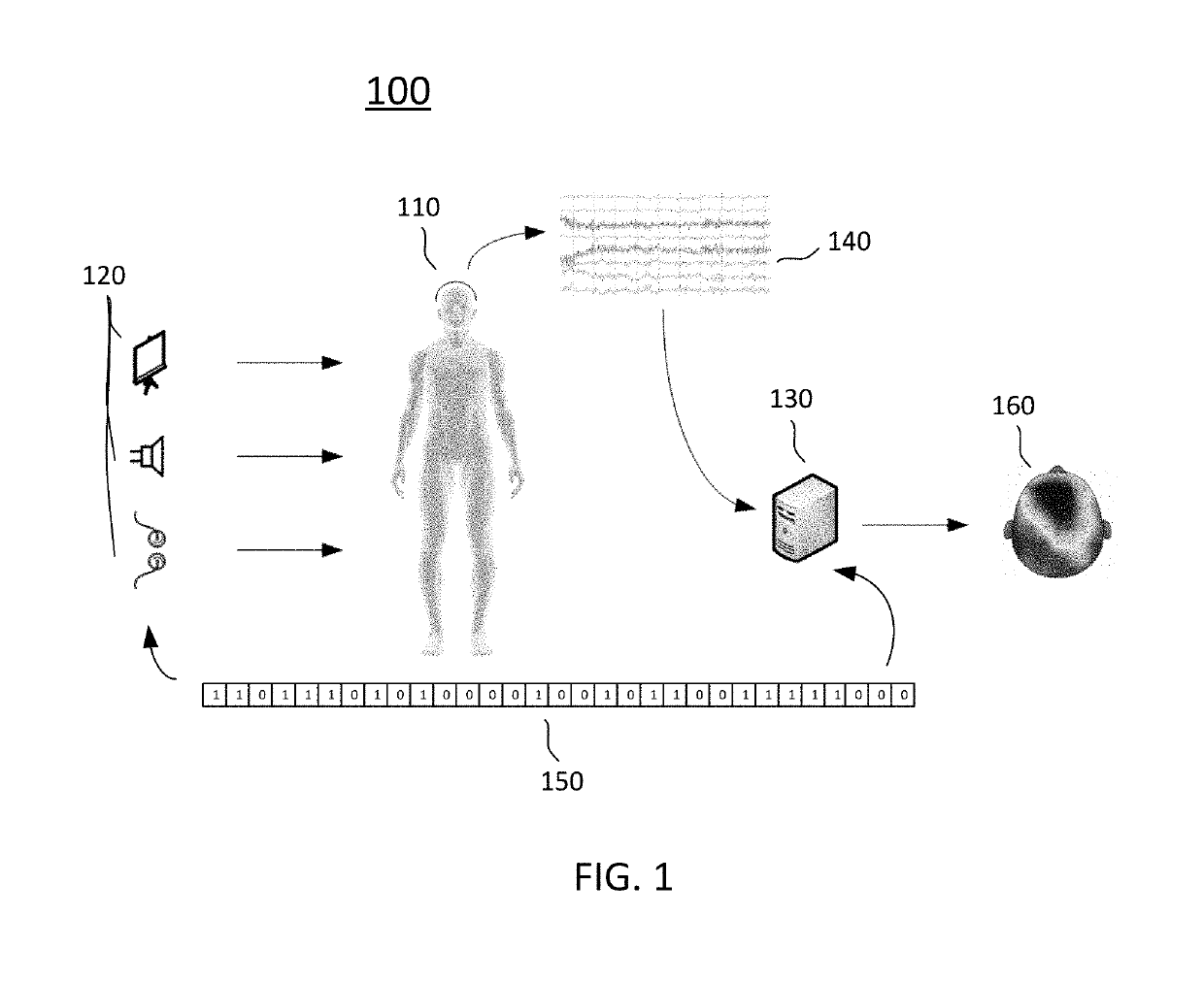
[0011]FIG. 1 shows a schematic diagram of a brain mapping system 100 illustrated according to an embodiment of the present invention. The brain mapping system 100 includes a brain signal acquisition device 110, a variety of stimulators 120, and a processor 130. The signal acquisition device 110 includes sensors that collect brain signals 140 corresponding to different locations of the brain. The brain signals 140 can be electroencephalography (EEG) signals and magnetoencephalography (MEG) signals. The stimulators 120 generate a stimulus based upon a pseudorandom sequence 150 (e.g., maximum-length sequence) and is applied via visual, audio, mechanical, optical, or electrical medium. These can be computer screens, computerized goggles, a headphone, speakers, a vibrator, lights, an electrical stimulator or any other device that activates perceptual brain regions. The processor 130 can be a computer, a microprocessor, or application specific integrated circuits that are designed to proc...


PUM


Abstract

A brain mapping system includes a brain signal acquisition device for collecting brain signals corresponding to different locations of the brain, a stimulator for generating a stimulus based upon a pseudorandom sequence, and a processor for segmenting the brain signals into a plurality of epochs and correlating features extracted from the epochs with the pseudorandom sequence to generate correlation functions, wherein a brain map is constructed by the correlation functions.

Description

BACKGROUND OF THE INVENTION1. Field of the Invention[0001]The invention relates to a brain mapping system and, more particularly, to a brain mapping system constructed by programmed peripheral stimulation.2. Description of the Related Art[0002]Techniques conventionally used for acquiring brain activity are limited by either their temporal or spatial resolutions and thus are infeasible for real-time monitoring. There is a need to develop more reliable systems with less limitations in order to gain more progress in the field of such clinical applications.BRIEF SUMMARY OF THE INVENTION[0003]One of the objects of the present invention is to provide a brain mapping system to improve the above-mentioned limitations.[0004]According to an embodiment of the invention, a brain mapping system includes a brain signal acquisition device for collecting brain signals from different locations of the brain, a stimulator for generating a stimulus based upon a pseudorandom sequence, and a processor fo...

Claims


Application Information

Patent Timeline
Patent Type & Authority Patents(United States)
IPC IPC(8): A61B5/04A61B5/0484
CPCA61B5/04008A61B5/0484A61B5/04012A61B5/04009A61B5/246A61B5/316A61B5/377A61B5/245
Inventor CHEN, CHIUN-FAN
Owner CHEN CHIUN FAN
Why Eureka
Try Eureka