Building automation scheduling system and method

a building automation and scheduling system technology, applied in the field of building automation systems, can solve the problems of difficult interpretation, inability to intuitively use, and difficult to interpret the program software to set up the schedule, and achieve the effect of easy error, easy error prevention, and simple structur

Active Publication Date: 2019-12-10
CRESTRON ELECTRONICS
View PDF19 Cites 6 Cited by
  • Summary
  • Abstract
  • Description
  • Claims
  • Application Information

AI Technical Summary

Benefits of technology

[0008]It is therefore a general aspect of the embodiments to provide a building automation scheduling system and method that allows a user to program scheduled events to control a vast amount of electronic devices and spaces of a building automation system in an intuitive, quick, and simple way.

Problems solved by technology

Building management systems utilize complicated software to control these devices on-demand or to create individualized automated scheduled events, for example to configure climate set points, lighting scenes, and shade levels for occupied and vacated states in one or more rooms.
Often the programming software to set up those schedules can be very confusing, difficult to interpret, and not intuitive to use.
Consequently, event scheduling has been a tedious process prone to errors due to vast amount of data entry and inability to usefully perceive and review the scheduled events.
As a result, building managers spend a considerable amount of time scheduling automated events of a building.
While some current solutions attempt to simplify the event scheduling process, these are inadequate.
There is no meaningful way to control the lights in between these two times. Hundreds or even thousands of events may be required to program the building automation system property.
While the existing systems may give custom and vast amount of control options, in most cases a majority of these control options are not even utilized.
This occurs because the current event scheduling solutions are cumbersome and confusing to set up, and even more cumbersome to visualize.

Method used


Image

  • Building automation scheduling system and method
  • Building automation scheduling system and method
  • Building automation scheduling system and method

Examples


Embodiment Construction

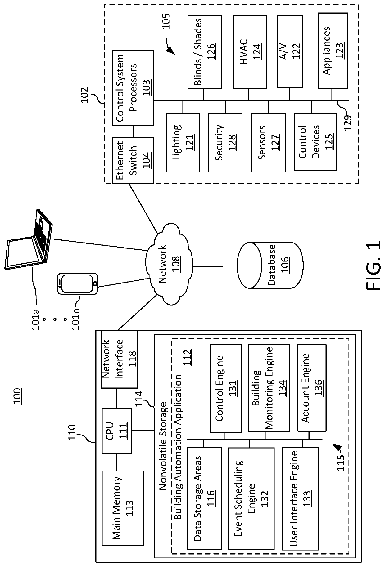
[0044]The embodiments are described more fully hereinafter with reference to the accompanying drawings, in which embodiments of the inventive concept are shown. In the drawings, the size and relative sizes of layers and regions may be exaggerated for clarity. Like numbers refer to like elements throughout. The embodiments may, however, be embodied in many different forms and should not be construed as limited to the embodiments set forth herein. Rather, these embodiments are provided so that this disclosure will be thorough and complete, and will fully convey the scope of the inventive concept to those skilled in the art. The scope of the embodiments is therefore defined by the appended claims. The detailed description that follows is written from the point of view of a control systems company, so it is to be understood that generally the concepts discussed herein are applicable to various subsystems and not limited to only a particular controlled device or class of devices.

[0045]Re...


PUM


Abstract

A building automation scheduling system and method for scheduling the control of electronic devices of a building automation system. The room scheduling system comprises a database including a plurality of space nodes identifying spaces located within a building and associated with one or more electronic devices installed within respective spaces in the building. The room scheduling system further comprises a processor in communication with the one or more electronic devices configured for classifying the space nodes by room categories, defining room states each comprising at least one control command for one or more electronic devices in a space, defining day patterns by assigning at least one room state to at least one room category over a course of a day, and assigning the day patterns to calendar days on a calendar.

Description

BACKGROUND OF THE INVENTIONTechnical Field[0001]Aspects of the embodiments relate to building automation systems, and more specifically to building automation scheduling system and method for scheduling electronic devices of a building automation system.Background Art[0002]Building automation and management are ever evolving to provide consumers with convenient and simple control and monitoring of various mechanical and electrical equipment within a building through building automation systems (BAS), also known as building management systems (BMS) and energy management systems (EMS). Building automation systems provide comfort, convenience, simplicity and security, as well as lower energy costs. They generally utilize a network of sensor and control devices distributed throughout a residential or commercial building to control and provide information on the mechanical and electrical equipment within the building. The system can control and monitor heating, ventilation and air condit...

Claims


Application Information

Patent Timeline
Patent Type & Authority Patents(United States)
IPC IPC(8): G06Q10/10G06F16/28G05B15/02H04L12/28
CPCG05B15/02G06Q10/1095G06F16/285H04L12/2816G05B2219/2642
Inventor JACOBSON, DOUG
Owner CRESTRON ELECTRONICS
Why Eureka
Try Eureka