Powered surgical stapling device

a stapling device and powered technology, applied in the direction of surgical staples, surgical forceps, cell components, etc., can solve the problems of fatigued hands of surgeons, limited user control of the stapling process,

Active Publication Date: 2019-12-03
COVIDIEN LP
View PDF506 Cites 670 Cited by
  • Summary
  • Abstract
  • Description
  • Claims
  • Application Information

AI Technical Summary

Problems solved by technology

Current known devices can typically require 10-60 pounds of manual hand force to clamp tissue and deploy and form surgical fasteners in tissue which, over repeated use, can cause a surgeon's hand to become fatigued.
However, these motor powered devices only provide for limited user control of the stapling process.

Method used


Image

  • Powered surgical stapling device
  • Powered surgical stapling device
  • Powered surgical stapling device

Examples


Embodiment Construction

[0062]Embodiments of the presently disclosed powered surgical instrument are now described in detail with reference to the drawings, in which like reference numerals designate identical or corresponding elements in each of the several views. As used herein the term “distal” refers to that portion of the powered surgical instrument, or component thereof, farther from the user while the term “proximal” refers to that portion of the powered surgical instrument or component thereof, closer to the user.

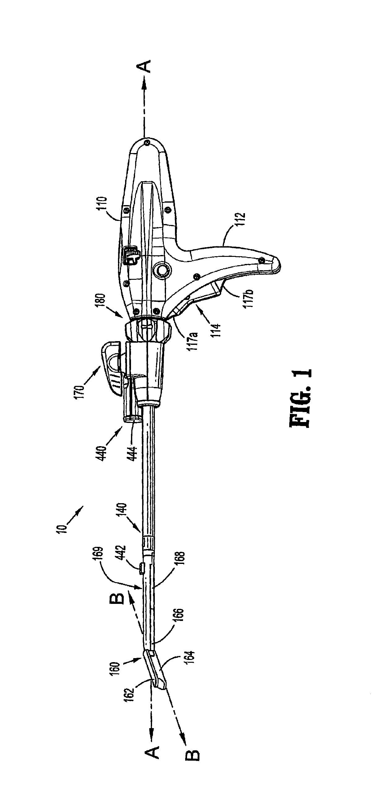
[0063]A powered surgical instrument, e.g., a surgical stapler, in accordance with the present disclosure is referred to in the figures as reference numeral 10. Referring initially to FIG. 1, powered surgical instrument 10 includes a housing 110, an endoscopic portion 140 defining a first longitudinal axis A-A extending therethrough, and an end effector 160, defining a second longitudinal axis B-B extending therethrough. Endoscopic portion 140 extends distally from housing 110 and the end e...


PUM


Abstract

A surgical stapler includes a handle assembly, an end effector, a firing rod disposed in mechanical cooperation with the end effector, a drive motor coupled to the firing rod, a sensor, and a controller. The end effector includes a first and second jaw member moveable relative to one another. The first jaw member includes a surgical fastener and the second jaw member includes an anvil. The drive motor is configured to advance the firing rod to cause the first and second jaw members to clamp tissue and to eject a surgical fastener. The surgical stapler includes a sensor that is configured measure a clamping force exerted on tissue by the first and second jaw members. The controller control a speed of the drive motor based on the measured clamping force.

Description

CROSS-REFERENCE TO RELATED APPLICATIONS[0001]This application is a continuation-in-part of U.S. patent application Ser. No. 14 / 598,586, which was filed on Jan. 16, 2015, which is a continuation-in-part of U.S. patent application Ser. No. 13 / 788,293, which was filed on Mar. 7, 2013, which is a continuation-in-part of U.S. patent application Ser. No. 12 / 189,834, which was filed on Aug. 12, 2008, now abandoned, which claims the benefit of, and priority to, U.S. Provisional Patent Application Ser. No. 60 / 997,854, which was filed on Oct. 5, 2007. The entire contents of each of the foregoing applications are hereby incorporated by reference herein.BACKGROUND[0002]1. Technical Field[0003]The present disclosure relates to a surgical stapler for implanting mechanical surgical fasteners into the tissue of a patient, and, in particular, to a surgical stapler which is powered by a motor for firing surgical fasteners into tissue and a feedback controller for controlling the stapler in response t...

Claims


Application Information

Patent Timeline
Patent Type & Authority Patents(United States)
IPC IPC(8): A61B17/068H02P7/29A61B17/00
CPCH02P7/29A61B2017/00022A61B2017/00734A61B2017/00473A61B2017/00106A61B2017/00199A61B2017/00057A61B2017/00115A61B17/07207A61B2017/00017A61B2017/00066A61B2017/00084A61B2017/00119A61B2017/00203A61B2017/00367A61B2017/00398A61B2017/00477A61B2017/2927A61B90/92A61B90/98A61B2090/037A61B2090/064A61B2090/066A61B2090/067A61B2090/0807A61B2090/0808A61B2090/0814A61B2090/306A61B2090/309H01M10/637H01M50/213H01M50/24Y02E60/10
Inventor ZEMLOK, MICHAEL A.LECH, RICHARDBANERJEE, SAUMYA
Owner COVIDIEN LP
Why Eureka
Try Eureka