Device and method for the automated picking up and laying of a segment to form a lining of a tunnel

a technology of automated picking up and laying, which is applied in the direction of shaft lining, shaft equipment, instruments, etc., can solve the problems of inability to accurately and repeatably position the segment, the operator(s) in the segment laying area are at risk of their safety, and the task is also particularly difficul

Active Publication Date: 2019-11-12
BOUYGUES TRAVAUX PUBLICS SA
View PDF3 Cites 3 Cited by
  • Summary
  • Abstract
  • Description
  • Claims
  • Application Information

AI Technical Summary

Benefits of technology

[0026]One object of the invention is to design a device for the automated laying of a segment that allows increasing the safety of the operators and the productivity by minimizing the intervention of an operator, minimizing the time for laying each segment and by improving the laying accuracy. This device must allow the laying of a complete ring, including the first and the last segment constituting the ring, whether it is a universal ring or not. Furthermore, said device must be compatible with an erector of a tunnel-boring machine of the market. Finally, said device must be compact and easy to install.
[0051]In a particularly advantageous manner, said method allows the automated laying of a complete ring of segments, said method being implemented for the set of segments constituting said ring.

Problems solved by technology

On the one hand, the presence of one or several operator(s) in the segment laying area presents a risk for their safety.
This task is also particularly difficult since it imposes multiple displacements to the operator.
As the erector is a hydraulic machine of great capacity and great range, with operatively important arrows, its positioning is not accurate and repeatable.
These defects are accentuated by the high degree of wear and the significant increase in the operating clearances over the service life of the tunnel-boring machine.
However, this device does not allow fully automating the laying of the segment, the approximate placement remaining performed by an operator.
In addition, this device does not allow controlling the quality of laying of the segment (said quality to be considered according to different degrees of freedom).
However, the times for processing such images are relatively long, which penalizes the time for laying each segment.
In addition, this device does not take into account any possible angular offset of the segment to be laid relative to the segment previously laid.
However, the erector described in this document has been designed specifically and the automation it provides is therefore not adaptable to an existing erector of a tunnel-boring machine of the market.
Finally, none of the aforementioned documents mentions the placement of the first segment or that of the key (last segment allowing to close the ring in the case of a universal ring), which has a more important complexity of placement.

Method used


Image

  • Device and method for the automated picking up and laying of a segment to form a lining of a tunnel
  • Device and method for the automated picking up and laying of a segment to form a lining of a tunnel
  • Device and method for the automated picking up and laying of a segment to form a lining of a tunnel

Examples


Embodiment Construction

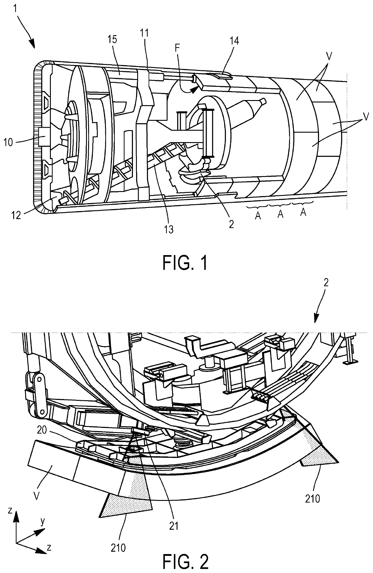
[0059]FIG. 1 is a partial cross-sectional overall view of the rear part of a tunnel-boring machine shield for which the invention is likely to be implemented, being specified that the invention is not limited in terms of type of tunnel-boring machine (earth-pressure tunnel-boring machine, mud-pressure tunnel-boring machine, etc.).

[0060]In a manner known per se, the tunnel-boring machine 1 comprises, in its front part, a rotary cutting head 10 and provided with cutting tools, intended for the felling of the ground.

[0061]The cutting head 10 is fixed to the front of a shield 11 which provides protection and sealing of the excavation work.

[0062]A felling chamber 12 in which the cuttings from the cutting front are transferred is at the rear of the cutting head 10.

[0063]The cuttings can be discharged from the felling chamber by means of a discharge screw 13, at the outlet of which they are deposited on a conveyor in order to be evacuated. According to the type of the tunnel-boring machine...


PUM


Abstract

The invention relates to a device for the automated picking up and placing of a segment forming the lining of a tunnel, intended to be coupled to a tunnel-boring machine (1) provided with a segment erector (2), comprising:—a controller designed to communicate with an automated system of the tunnel boring machine, suitable for controlling the actuation of the erector; and—a three-dimensional vision system comprising at least four laser profilometers; the controller is designed to receive a segment positioning plan and to determine, from the analysis data of the three-dimensional vision system, the measurement data of the erector sensors and the segment positioning plan, an erector trajectory for positioning the segment (V) to be placed in alignment with a segment and / or ring (A) of segments already placed, and to communicate movement commands to the automated system of the tunnel boring machine, for actuating the erector to pick up the segment to be placed and move it according to the above trajectory.

Description

FIELD OF THE INVENTION[0001]The present invention relates to a device for the automated picking up and laying of a segment intended to be coupled to a tunnel-boring machine provided with a segment erector, as well as to a method for the automated picking up and laying of segments implementing such a device.BACKGROUND OF THE INVENTION[0002]The lining of a tunnel generally consists of prefabricated segments (voussoirs) arranged in the form of a plurality of successive rings.[0003]As the tunnel-boring machine advances, a new ring is constructed by successively assembling a plurality of segments against a previously laid ring.[0004]The front face of each new ring (that is to say, the face oriented towards the cutting head of the tunnel-boring machine) serves as a bearing surface for thrust cylinders located at the rear of the tunnel-boring machine shield (that is to say on the opposite side to the cutting head) and intended to exert the thrust necessary to dig the excavated ground.[0005...

Claims


Application Information

Patent Timeline
Patent Type & Authority Patents(United States)
IPC IPC(8): E21D11/40G01B11/30E21D9/00
CPCE21D9/003E21D11/403G01B11/306E21D9/004
Inventor MOUTON, LUCASDEMUYNCK, NICOLAS
Owner BOUYGUES TRAVAUX PUBLICS SA
Why Eureka
Try Eureka