Temperature controlled transport enclosure with tracking technology utilizing thermoelectric devices

a technology of thermoelectric devices and temperature control, applied in the field of temperature control transport enclosures with tracking technology utilizing thermoelectric devices, can solve the problems of degradation of products and damage to some products, and achieve the effects of enhancing control and interface functions, and reducing the risk of damag

Active Publication Date: 2019-11-05
GROGAN CHARLES PAUL
View PDF17 Cites 0 Cited by
  • Summary
  • Abstract
  • Description
  • Claims
  • Application Information

AI Technical Summary

Benefits of technology

[0020]It is an object of this invention to provide a portable, self-contained, automatic temperature-controlled enclosure which can control the temperature of a few bottles of wine in a given temperature range.
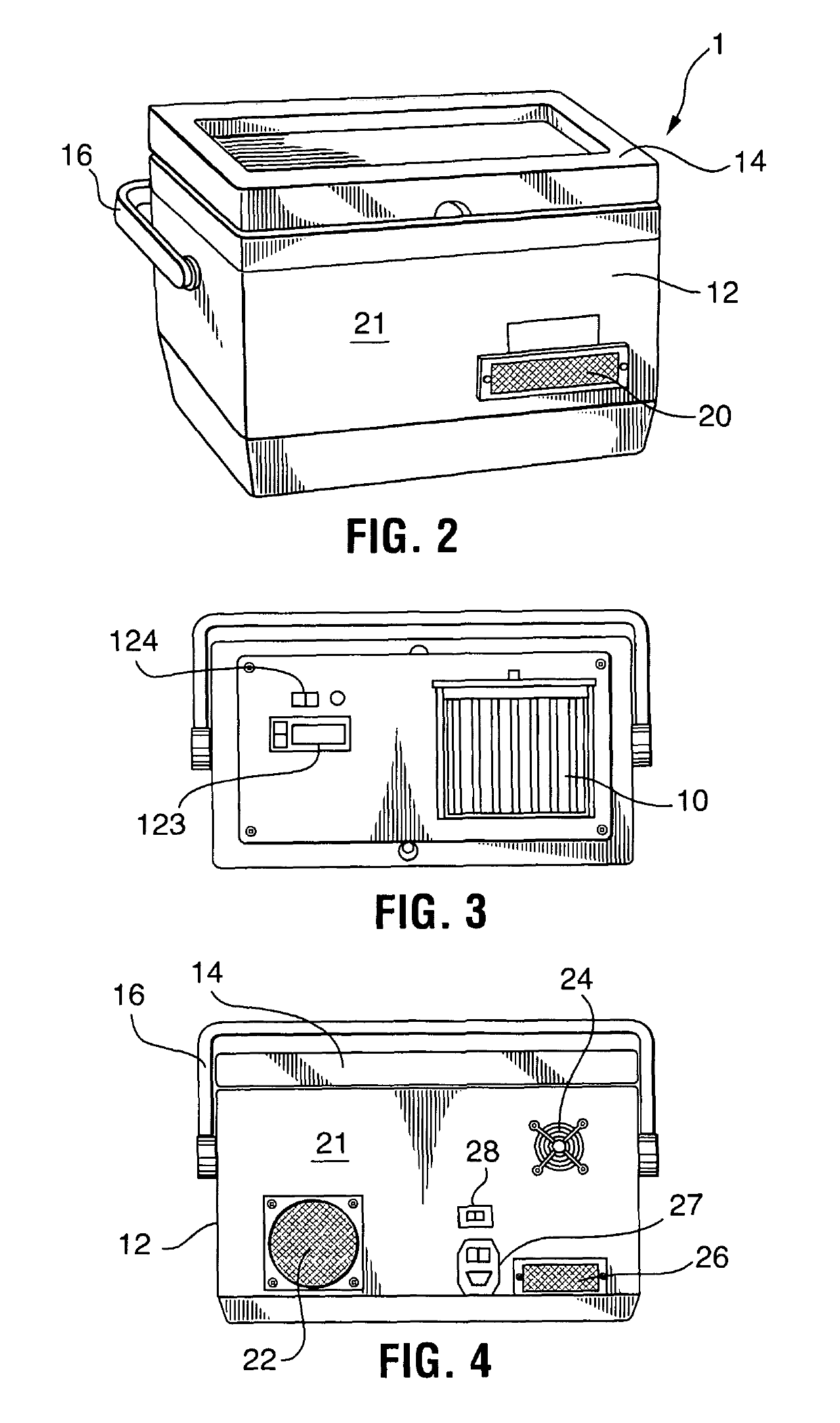
[0028]The user opens the top cover turning on the device through the operator's panel, and setting the desired temperature via buttons on the temperature controller, using the display to view the settings. Once set, the user would place his material requiring transport into the cavity, and then close the cover. Operating instructions for the device will recommend that the material to be transported already be at or close to the desired temperature from its non-portable storage location. This will maximize the operational time of the device.
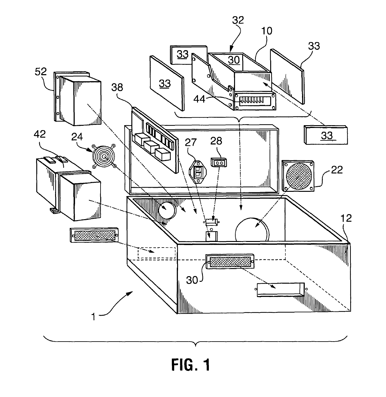
[0036]The power supply is housed in a thermal heat chimney designed to draw outside ambient air into the power supply and exhaust the waste heat external to the Carrier enclosure. This is facilitated by at least one fan that draws air across a custom heat sink 44 attached to the power supply thermal interface. The use of the Thermal Chimney minimizes any effects of waste heat from the power supply from heating the internal space of the Carrier enclosure.Thermal Transfer Device / Thermal Cavity Module
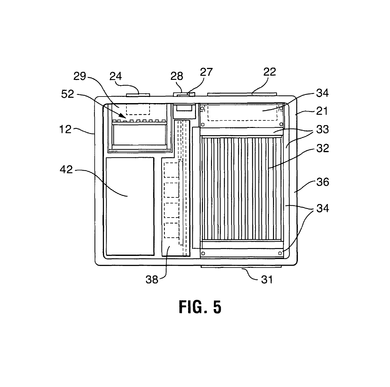
[0037]The Thermal Transfer device / Thermal cavity module is a bi-directional heating, cooling, and energy transfer device based upon the Peltier effect for thermal energy conversion. In the device, this module is a bi-directional heat flow transfer device, consisting of multiple industrial thermo-electric coolers (TEC), or Peltier devices, mounted to transfer device / thermal cavity assembly consisting of a custom heat sink on one side and an application-specific custom heat manifold on the other side. The heat transfer device transfers the cooling or heating energy from the TEC devices through the manifold and radiates it to the cavity. The temperature is monitored in the cavity for feedback to the Temperature Controller. The bi-directional heat flow capability is facilitated through the polarity of power applied to the TEC devices. Power routing to the module flows through the Auxiliary Electronics module, controlled by the Temperature Controller and user interface. The heat sink and thermal transfer device / enclosure utilize high thermally-conductive aluminum alloys to efficiently move heat through the TEC system to the cavity utilizing a combination of conductive and convective heat transfer principles. Forced air flow for the heat sink side is provided by a ducted fan controlled through from the Auxiliary Electronics module. The forced air is vented to the outside to prevent heat buildup inside the ATCE carrier enclosure. This module is an integral part of the internal cavity and the manifold is uniquely designed to maximize thermal flow from the TEC devices to the cavity space.
[0043]The Enclosure is constructed in a manner similar to a dual-wall, foam cavity portable cooler. Cooler wall conduits and penetrations are made for airflow inlets via front inlet grill and outlets and external power connections. The enclosure, from hereon, also referred to as the automatic temperature controlled enclosure (ATCE) carrier utilizes a top panel for unit controls, monitoring, and access to the temperature controlled cavity. Access to the top panel is made by simply opening the lid to the enclosure. Additional foam insulation panels or pads with reflective foil are utilized around the thermal transfer device or thermal cavity subassembly to further stabilize the thermal cavity temperature-controlled cavity and to force the convective heat / cool energy transfer to the desired thermal cavity space. Internal areas with controlled airflow cavities are mounted in the cooler thermal cavity with foam edge boundaries, which effectively seal the areas against airflow escape. This insulation, along with the dual-wall cooler thermal cavity construction, provide resistance against external ambient temperatures.

Problems solved by technology

Quality problems may occur when transporting wines, beer, or other temperature sensitive beverages, food, medicines, or other biodegradable materials if the products are subjected to temperatures above a level resulting in degradation of the product.
Even variable temperature levels or humidity levels may result in damage to some products.

Method used


Image

  • Temperature controlled transport enclosure with tracking technology utilizing thermoelectric devices
  • Temperature controlled transport enclosure with tracking technology utilizing thermoelectric devices
  • Temperature controlled transport enclosure with tracking technology utilizing thermoelectric devices

Examples


Embodiment Construction

[0070]The terminology used herein is for the purpose of describing particular example embodiments only and is not intended to be limiting. As used herein, the singular forms “a,”“an,” and “the” may be intended to include the plural forms as well, unless the context clearly indicates otherwise. The terms “comprises,”“comprising,”“including,” and “having,” are inclusive and therefore specify the presence of stated features, integers, steps, operations, elements, and / or components, but do not preclude the presence or addition of one or more other features, integers, steps, operations, elements, components, and / or groups thereof. The method steps, processes, and operations described herein are not to be construed as necessarily requiring their performance in the particular order discussed or illustrated, unless specifically identified as an order of performance. It is also to be understood that additional or alternative steps may be employed.

[0071]When an element or layer is referred to...


PUM


Abstract

A portable, self-contained, temperature-controlled enclosure capable of maintaining a constant, user-specified temperature within the enclosure independent of the outside environment. The device is ideal for the transport of material that is highly temperature sensitive and requires a stable temperature environment. The portable enclosure includes capability of cellular and GPS location beacon identification, comprehensive internal status and operation monitoring, and wireless communication capability of the device status, temperature and humidity parameters, and location using BLUE TOOTH, WIFI and / or cellular technology. The system is powered by an onboard rechargeable battery, external DC power, or external AC power.

Description

[0001]This application claims priority from U.S. Provisional Patent Application No. 62 / 390,736 filed on Apr. 7, 2016 which is incorporated by reference herein in it's entirety.TECHNICAL FIELD[0002]The present invention relates to the field of portable containers capable of maintaining the contents at a selected temperature and transmitting the location, status and health of the contents using the cellular communication network using GPS tracking to determine the present location.BACKGROUND OF THE INVENTION[0003]Quality problems may occur when transporting wines, beer, or other temperature sensitive beverages, food, medicines, or other biodegradable materials if the products are subjected to temperatures above a level resulting in degradation of the product. Even variable temperature levels or humidity levels may result in damage to some products. For instance, it is desirable to maintain a pre-selected temperature range for maintaining the integrity of wines. Storing and serving win...

Claims


Application Information

Patent Timeline
Patent Type & Authority Patents(United States)
IPC IPC(8): F25B21/04B65D81/18F25D29/00F25B21/02B65D81/38F25D11/00
CPCF25B21/02F25D29/00F25B21/04B65D81/18F24F2221/48F25D2700/08F25D11/003B65D81/3825F25D2331/809
Inventor GROGAN, CHARLES PAUL
Owner GROGAN CHARLES PAUL
Why Eureka
Try Eureka