
Portable viscometer

a viscometer and portability technology, applied in the field of viscometers, can solve the problems of not knowing or calculating the shear rate of almost all non-newtonian liquids, unable to measure the true viscosity of most non-newtonian liquids with ill-defined test conditions,

Active Publication Date: 2019-10-22
RHEOSENSE
View PDF111 Cites 1 Cited by
  • Summary
  • Abstract
  • Description
  • Claims
  • Application Information

AI Technical Summary

Benefits of technology

Enables accurate and rapid measurement of true viscosity for small liquid samples, reducing cleaning time and sample waste, and allowing for on-line applications without the need for extensive sample preparation or expensive equipment.

Problems solved by technology

However, in many cases, viscosity is measured under ill-defined test condition so that shear rate cannot be known or calculated.
However, a “constitutive equation” is not known for almost all Non-Newtonian liquids.
Therefore, true viscosity can not be measured with ill-defined test conditions for most non-Newtonian liquids.
However, because of the non-universality of the apparent viscosity measurement, a correlation of the apparent viscosity of a specific sample measured with a specific method with the true viscosity has to be found separately when desired.
Therefore they are usually expensive.
Further, large amounts of samples are usually required for viscosity measurement with a rheometer.
Also, rheometers are not well suited for on-line applications.
However, use of two capillaries makes the capillary viscometers bulky and / or time consuming.
In summary, most viscosity measurement techniques yield apparent viscosity and require relatively large volumes of sample.
Such a cleaning is time consuming so that viscosity measurements typically take about 30 minutes from the set-up to the test.
The larger sample volume requirement with current techniques also increases the cleaning time and waste.
Therefore, there is no genuine portable viscometer which measures true viscosity for samples in small quantity and in a fast manner.

Method used


Image

  • Portable viscometer
  • Portable viscometer
  • Portable viscometer

Examples


Embodiment Construction

)

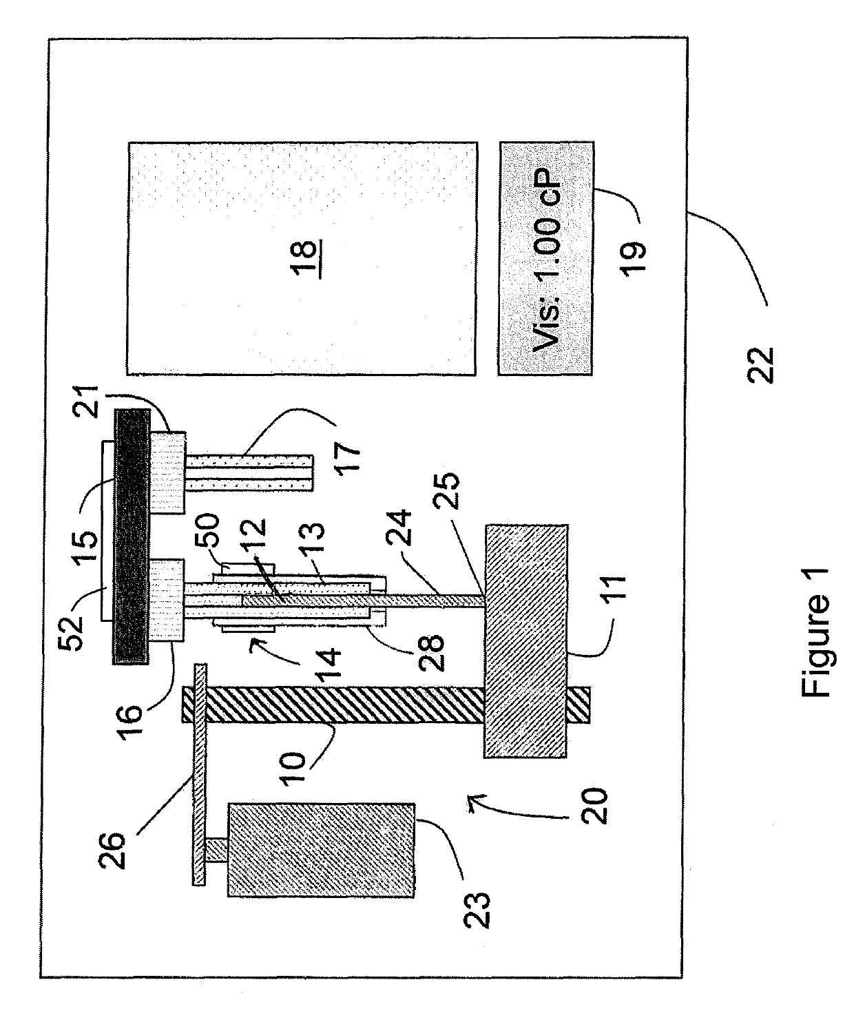
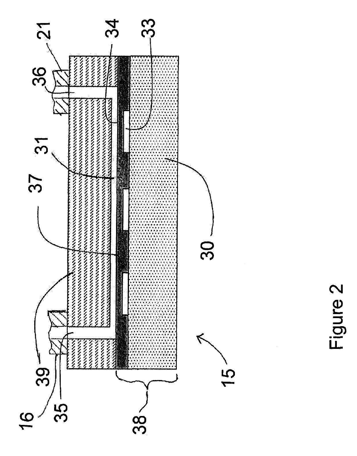
[0020]The invention provides an improved viscometer which is portable, easier-to-use, more accurate, and a faster way of measuring the viscosities of liquid samples than prior art viscometers. Referring to FIG. 1, the viscometer 22 includes a precision pump, indicated generally by reference number 20, a liquid container 14 for supplying a sample of the liquid for which a viscosity measurement is desired, a flow-through viscosity sensor 15, a controller 18, and a display 19.

[0021]The pump 20 works in conjunction with a sample container shown and referred to as a pipette 14 having a pipette barrel or body 13 and a plunger 12 slidably positioned in the pipette barrel 13 with plunger end portion 24 extending from an end of the barrel 13. The pipette 14 may be removably positioned and held in the viscometer by a mounting mechanism 28 so the pipette can be removed, filled with a sample of liquid to be tested, and replaced into the mounting mechanism of the viscometer, or can be removed a...


PUM

PropertyMeasurementUnit
depthaaaaaaaaaa
depthaaaaaaaaaa
lengthaaaaaaaaaa

Abstract

A portable viscometer includes a pump mechanism which cooperates with a positive displacement sample container referred to as a positive displacement pipette, for dispensing, at a known flow rate, a sample of liquid for which viscosity is desired to be determined. The dispensed liquid flows through a flow through miniature viscosity sensor having at least two pressure sensors which measure the pressure drop of the liquid as it flows through a rectangular flow channel, the pressure drop at the known flow rate being proportional to the viscosity. A controller controls operation of the viscometer and processes sensor data, and the resulting measurements of viscosity can be displayed on a display. The positive displacement pipette is removably positioned in the viscometer so that it can be removed from the viscometer when a viscosity test is completed and replaced with another positive displacement pipette containing another liquid to be tested.

Description

PRIORITY CLAIM[0001]This application claims the benefit of provisional application Ser. No. 61 / 327,889, filed Apr. 26, 2010, entitled “Portable Rheometer,” which is incorporated herein by reference.BACKGROUND[0002]Field of the Invention[0003]This invention is in the field of viscometers that measure viscosity of liquids utilizing a flow-through type viscosity sensor.[0004]State of the Art[0005]Viscosity is a measure of resistance of liquid to flow and its value depends on the rate of deformation for Non-Newtonian liquids as described in Dynamics of Polymeric Liquids, Vol. 1, 1987, authored by R. B. Bird, R. C. Armstrong, and O. Hassager. The rate of deformation is given by a shear rate in a unit of (time)−1. The viscosity measured at a known shear rate is “true” viscosity. The dependence of the true viscosity on shear rate is a viscosity curve which characterizes material and is an important factor to consider for efficient processing. However, in many cases, viscosity is measured u...

Claims


Application Information

Patent Timeline
Patent Type & Authority Patents(United States)
IPC IPC(8): G01N11/08
CPCG01N11/08
Inventor BAEK, SEONG-GI
Owner RHEOSENSE
Learn More