Spread, span and wheel alignment gauge

Active Publication Date: 2019-10-22
RED E ROW PROD LLC
View PDF17 Cites 2 Cited by
  • Summary
  • Abstract
  • Description
  • Claims
  • Application Information

AI Technical Summary

Benefits of technology

The invention is a device and method for accurately adjusting the wheels on equipment within tracks to minimize friction and ensure the best performance. The device comprises two rigid gauge bars connected by an adjustable scissor link, and a measuring gauge that can be used to position a tape measure to determine the spread of the boat. The method involves using the tracks to locate the center point, which is then used to determine precise rigging, and then adjusting the wheel settings to ensure the wheel is positioned correctly. The technical effect of this invention is that it provides a precise and efficient way to adjust the wheels on equipment within tracks for optimal performance.

Problems solved by technology

If not properly positioned in the center of the track, the rub of the wheels causes unwanted friction, imposing axial load on the wheels.
This causes the wheel bearings to wear more than if they were subject only to radial load.
Wheels particularly, and track to a lesser extent, can wear out, becoming misshapen, uneven, and inefficient.
With rowing boats, these components are expensive to replace, and in racing environments even small amounts of friction translates to drag and lost time.
It requires greater effort by the rower and slows movement.
However, existing devices and measuring instruments do not provide for accurate measurements in that they measure relative to parts of the rigging that do not capture true center of the spread and span.
Rowing boat gauges that measure from the pin to the heal of a rowing shoe provide a setting relative to a rower's hip, which can negatively impact rigging, especially performance of the sliding seat.
Rigger spread measuring instruments that provide sliding seat dimensions from or between gunnels also may not capture the center of the rower, the more critical point for rigging accurately.
Also, devices requiring sensors, lasers and other electronic equipment can have power or other technical constraints, particularly in wet settings.

Method used


Image

  • Spread, span and wheel alignment gauge
  • Spread, span and wheel alignment gauge
  • Spread, span and wheel alignment gauge

Examples


Embodiment Construction

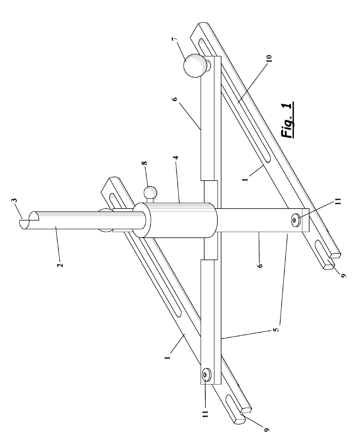
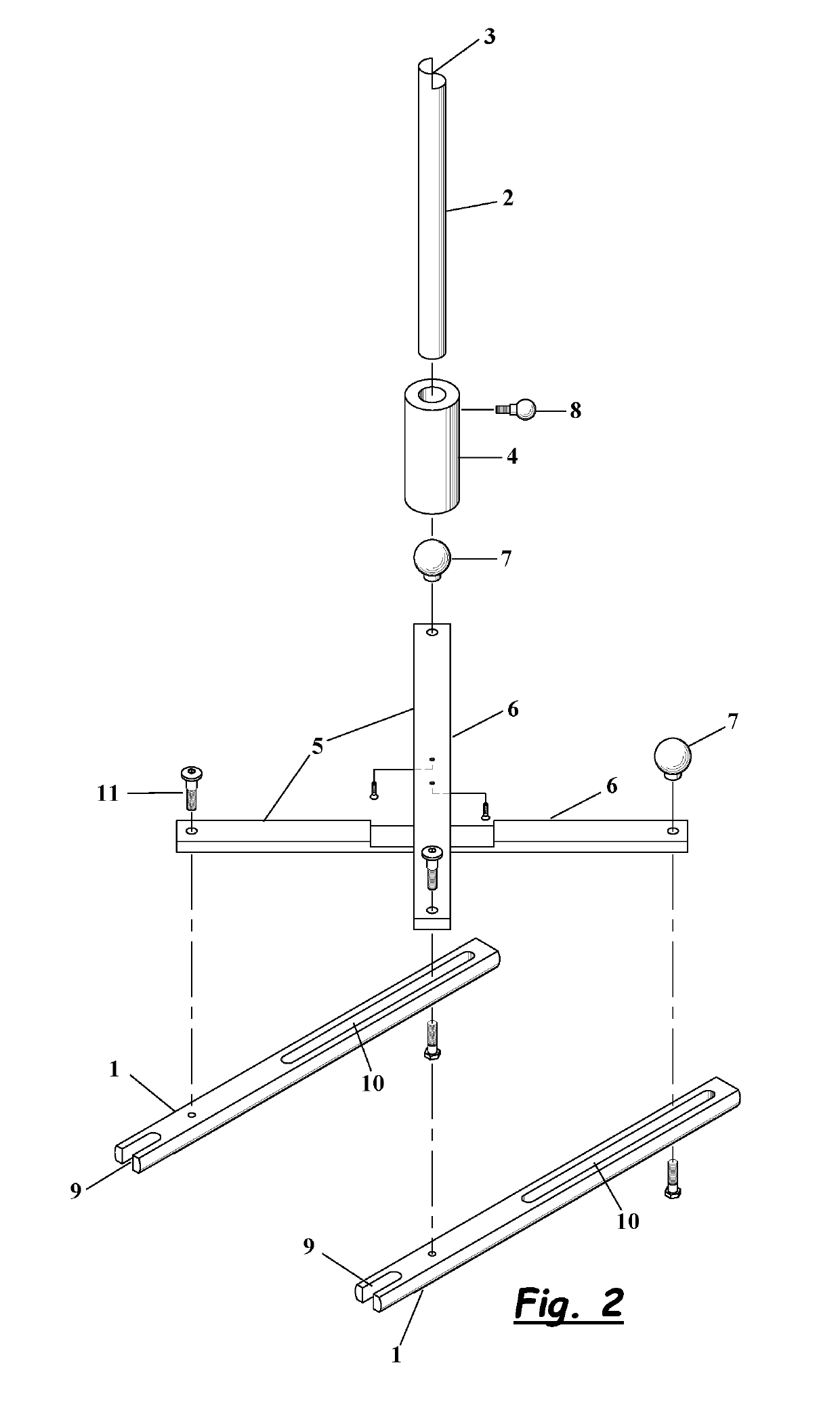
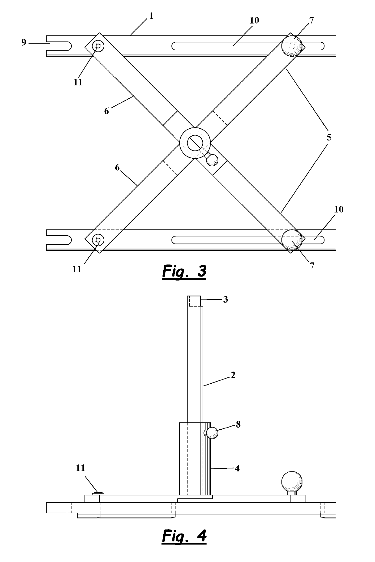
[0039]The following description of the drawings explains and further defines the invention disclosed with reference to each of the drawings. The figures and drawings form part of the present specification and are included to further demonstrate certain aspects of the present claimed subject matter, and should not be used to limit or define the present claimed subject matter.

[0040]The present claimed subject matter may be better understood by reference to one or more of these drawings in combination with the description of embodiments presented herein. Consequently, a more complete understanding of the present embodiments and further features and advantages thereof may be acquired by referring to the following description taken in conjunction with the accompanying drawings. It should be appreciated that the present invention encompasses multiple inventive concepts that may be embodied in a variety of contexts. This detailed description, read in conjunction with the accompanying drawi...


PUM


Abstract

The invention disclosed herein is a device, method of use and kit for measuring and precisely setting the dimensions in wheeled and tracked devices or vehicles. It is particularly well-suited for rowing boats and simulators thereof, including but not limited to sweep rowing and sculling watercraft. It introduces a novel gauge and process to adjust wheels within tracked environments to minimize friction and enhance equipment performance. Further, the device is capable of precise measurement of both spread and span dimensions in rowing watercraft to optimize rigging.

Description

CROSS-REFERENCE TO RELATED APPLICATIONS[0001]Not applicable.STATEMENT REGARDING FEDERALLY SPONSORED RESEARCH / DEVELOPMENT[0002]Not applicable.REFERENCE TO SEQUENCE LISTING, A TABLE, OR COMPUTER PROGRAM LISTING COMPACT DISC APPENDIX[0003]Not applicable.BACKGROUND OF THE INVENTION[0004]The present invention relates to the field of measuring and measurement devices. Specifically, the invention comprises a device, system and method for measuring and precisely setting the dimensions in wheeled and tracked devices or vehicles, and is particularly well-suited for rowing boats and simulators thereof, including but not limited to sweep rowing and sculling watercraft.[0005]Devices, machines and vehicles that include wheels operational within tracks require proper alignment of the tracks and wheels to optimize function, minimize friction and reduce wear-and-tear with use. In rowing watercraft, particularly when use includes racing or competitive rowing, precisely setting or rigging the various ...

Claims


Application Information

Patent Timeline
IPC IPC(8): G01B3/20G01B5/00B63B35/73G01D21/02G01B3/10
CPCG01B3/20G01B5/0002B63B35/73G01B2003/1092G01B3/1084G01D21/02B63H16/02B63B34/00B63B34/30G01B5/0025G01B5/255B63H16/04G01B3/1092
Inventor SPERBER, PERRY R
Owner RED E ROW PROD LLC
Why Eureka
Try Eureka