
Automatically actuated door lock system

a technology of automatic actuation and door locks, which is applied in the direction of door/window fittings, wing accessories, wing arrangements, etc., can solve the problems of increasing the risk of spreading germs, increasing the time to move the door package into a full breakout position, etc., so as to reduce the potential for spreading germs, enhance the ability to move patient beds and equipment in and out of the room quickly and efficiently, and save time

Active Publication Date: 2019-09-10
ASSA ABLOY ENTRANCE SYST AB
View PDF56 Cites 8 Cited by
  • Summary
  • Abstract
  • Description
  • Claims
  • Application Information

AI Technical Summary

Benefits of technology

The automatic system saves time, reduces the risk of germ spread, and enhances access for patient beds and equipment by allowing door panels to pivot or swing open efficiently without manual intervention.

Problems solved by technology

The manual actuation of these latch mechanisms increases the risk of spreading germs, requires personnel to know where the manual latch mechanisms are located and how to operate them, and increases the time to move the door package into a full breakout position.

Method used


Image

  • Automatically actuated door lock system
  • Automatically actuated door lock system
  • Automatically actuated door lock system

Examples


Embodiment Construction

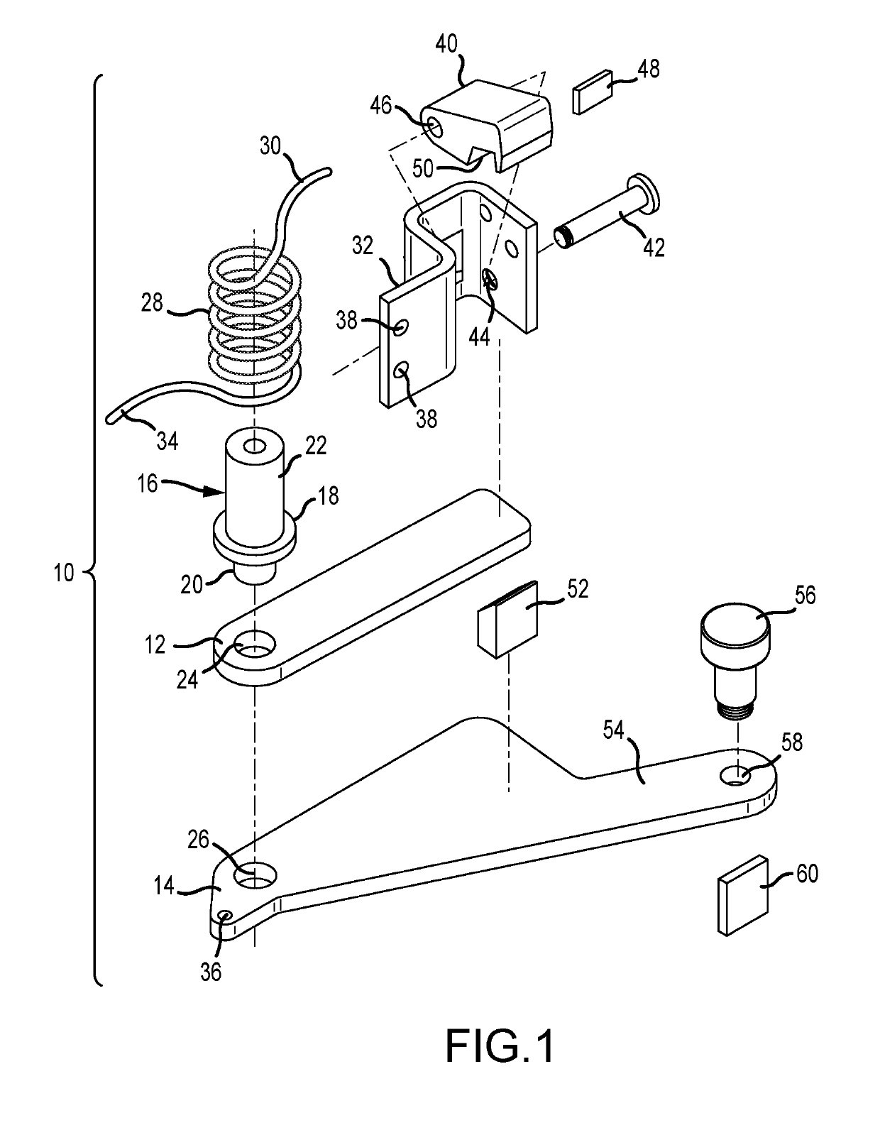
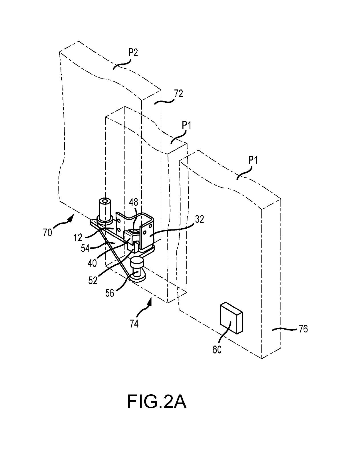
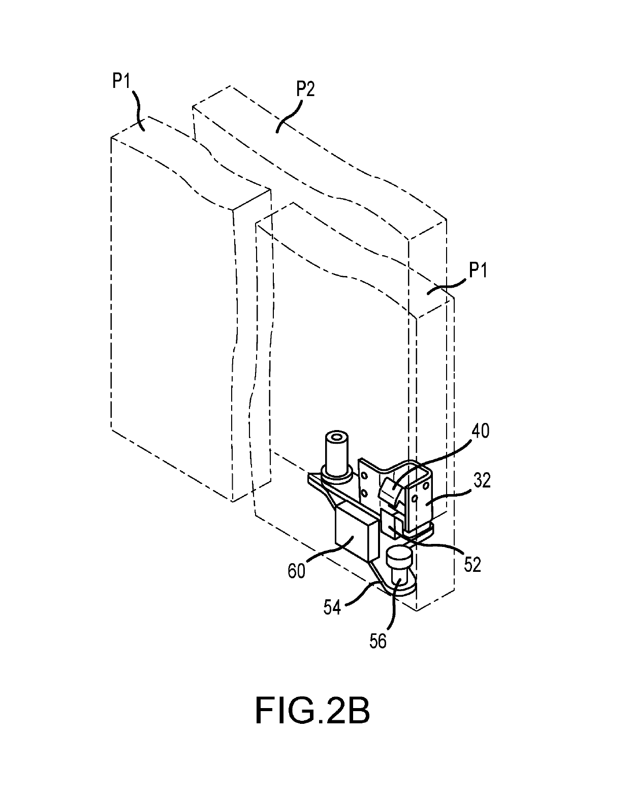
[0038]FIG. 1 is an exploded view of one embodiment of a lower latch assembly 10. As shown, the lower latch assembly 10 includes a fixed plate 12 and a swing arm 14 configured to pivot relative to the fixed plate 12 about the lower portion of a support post 16. The support post 16 has an outwardly extending flange 18 that separates the lower portion 20 from the upper portion 22. The lower portion 20 extends through an aperture 24 in the fixed plate and into an aperture 26 in the swing arm 14. The flange 18 abuts the fixed plate 12 and stabilizes the support post 16 within the apertures. A biasing spring 28 is positioned around the upper portion 22 of the support post 16 with one end 30 interconnected to a door mount 32 and the opposite end 34 interconnected to the swing arm 14 at aperture 36. The biasing spring 28 assists in maintaining alignment of the fixed plate 12 and swing arm 14 such that the swing arm 14 may pivot relative to the fixed plate 12 without binding. The fixed plate...


PUM


Abstract

A door package or door assembly includes multiple door panels. A top frame member has one or more tracks upon which one or more door panels may slide relative to a door opening to close the door opening when in a fully extended position and to open the doorway when in a retracted position. When in its retracted or open position, a plurality of door panels may also pivot about a pivot plate attached to the floor to a broken open position essentially perpendicular to the plane of the doorway opening. Upper and lower magnetic latch assemblies automatically decouple to permit pivoting of the entire door panel assembly when the panels are fully retracted, and when the panels are not fully retracted, are automatically actuated to prevent pivoting of the door panel assembly.

Description

RELATED APPLICATION[0001]The subject matter of the present disclosure is related to the content of U.S. Pat. No. 8,096,342 issued Jan. 17, 2012, the entirety of which is incorporated herein by reference.FIELD OF THE INVENTION[0002]The present application is directed to an automatically actuated lock or latch system used in connection with sliding or telescoping door panels that permits multiple door panels both to slide relative to each other in typical operating fashion and swing or pivot in combination increasing the doorway opening capability. While a primary end use for embodiments of the present application are patient room doorways in hospitals, including intensive care unit rooms, aspects of the present disclosure may be used in many other end use applications. In one embodiment, the system utilizes interacting magnets to couple and decouple door latching assemblies.BACKGROUND OF THE INVENTION[0003]Sliding or telescoping door systems have many applications. When the individua...

Claims


Application Information

Patent Timeline
Patent Type & Authority Patents(United States)
IPC IPC(8): E05D15/00E06B3/46E05B47/00E05D15/06E05B65/00E06B3/50E05D15/08
CPCE05D15/0621E05B47/004E05B65/0085E06B3/469E06B3/4636E06B3/509E05D15/08E05Y2900/132
Inventor WOLFE, JEFFREY A.
Owner ASSA ABLOY ENTRANCE SYST AB
Learn More