
Machine guidance for optimal working direction of travel

a technology of optimal working direction and machine guidance, applied in the direction of vehicle position/course/altitude control, process and machine control, instruments, etc., can solve the problems of limited success, large amount of input data, and large amount of processing resources, and achieve the effect of calculating spatial field efficiency and operating and spatial field efficiency

Active Publication Date: 2019-08-06
CROPZILLA SOFTWARE INC
View PDF23 Cites 2 Cited by
  • Summary
  • Abstract
  • Description
  • Claims
  • Application Information

AI Technical Summary

Benefits of technology

The system effectively reduces computational overhead and improves spatial field efficiency by focusing on the initial working direction, allowing for quicker recalculations and more efficient field coverage, even with varying farm implements and complex field geometries.

Problems solved by technology

The problem of determining the most efficient route to take when farming a field is one that has challenged generations of farmers.
Modern machine control promises to solve the problem, though despite many differing approaches, only limited success has been achieved.
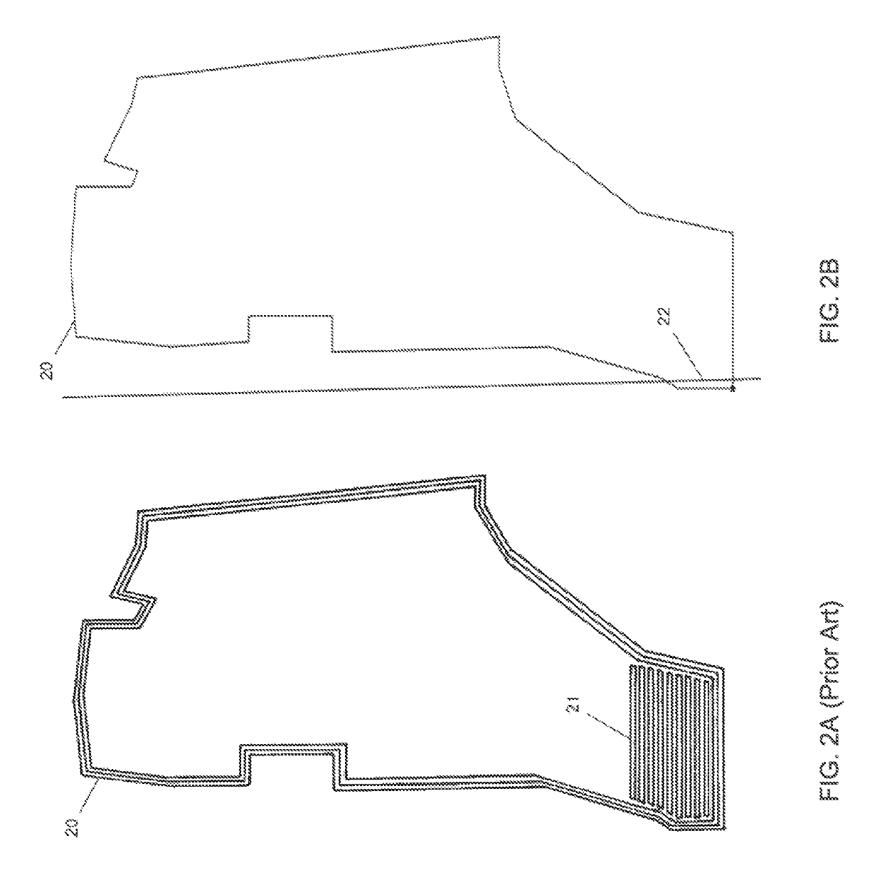
A drawback of these full path approaches is that calculating the full route over the entire field relies on relatively large amounts of input data in order to generate accurate results, and requires a relatively large amount of processing resources.
These aspects tend to adversely affect the speed with which routes are recalculated, such as when switching farm implements in the field.
While this approach may eliminate point rows, it tends to create some adverse operating conditions in the center section of the swath passes.
Effectively adjusting the swath width, by enabling or disabling rows, may be impractical when using equipment with a fixed width.
Combine equipment with a fixed width, a standing crop, and swath passes that have been adjusted so rows are disabled for less effective width and the problem turns into potentially destroying the standing crop instead of the swath pattern containing point rows.

Method used


Image

  • Machine guidance for optimal working direction of travel
  • Machine guidance for optimal working direction of travel
  • Machine guidance for optimal working direction of travel

Examples


Embodiment Construction

[0030]In the following detailed description, reference is made to the accompanying drawings that form a part hereof, and in which is shown by way of illustration, specific embodiments in which the invention may be practiced. These embodiments are described in sufficient detail to enable those skilled in the art to practice the invention, and it is to be understood that other embodiments may be utilized. It is also to be understood that structural, procedural and system changes may be made without departing from the spirit and scope of the present invention. In addition, well-known structures, circuits and techniques have not been shown in detail in order not to obscure the understanding of this description. The following detailed description is, therefore, not to be taken in a limiting sense, and the scope of the present invention is defined by the appended claims and their equivalents.

[0031]As used in the specification and in the appended claims, the singular forms “a”, “an”, and “...


PUM


Abstract

A system and method for determining the optimal machine working direction(s) of travel for a field boundary to be used in a guidance / navigation system for machine control includes, using specific field boundary information and machine specific information to spatially simulate travel path estimates over a plurality of splayed working directions of travel to determine the optimal working direction(s) of travel for the field boundary. Optimizing the spatial field efficiency by simulating travel path estimates to select an optimal working direction(s) of travel may then be used in accordance with a machine's guidance and / or navigation system, via an information transfer system, as the reference working direction(s) of travel for the machine to guide and control itself while performing fieldwork.

Description

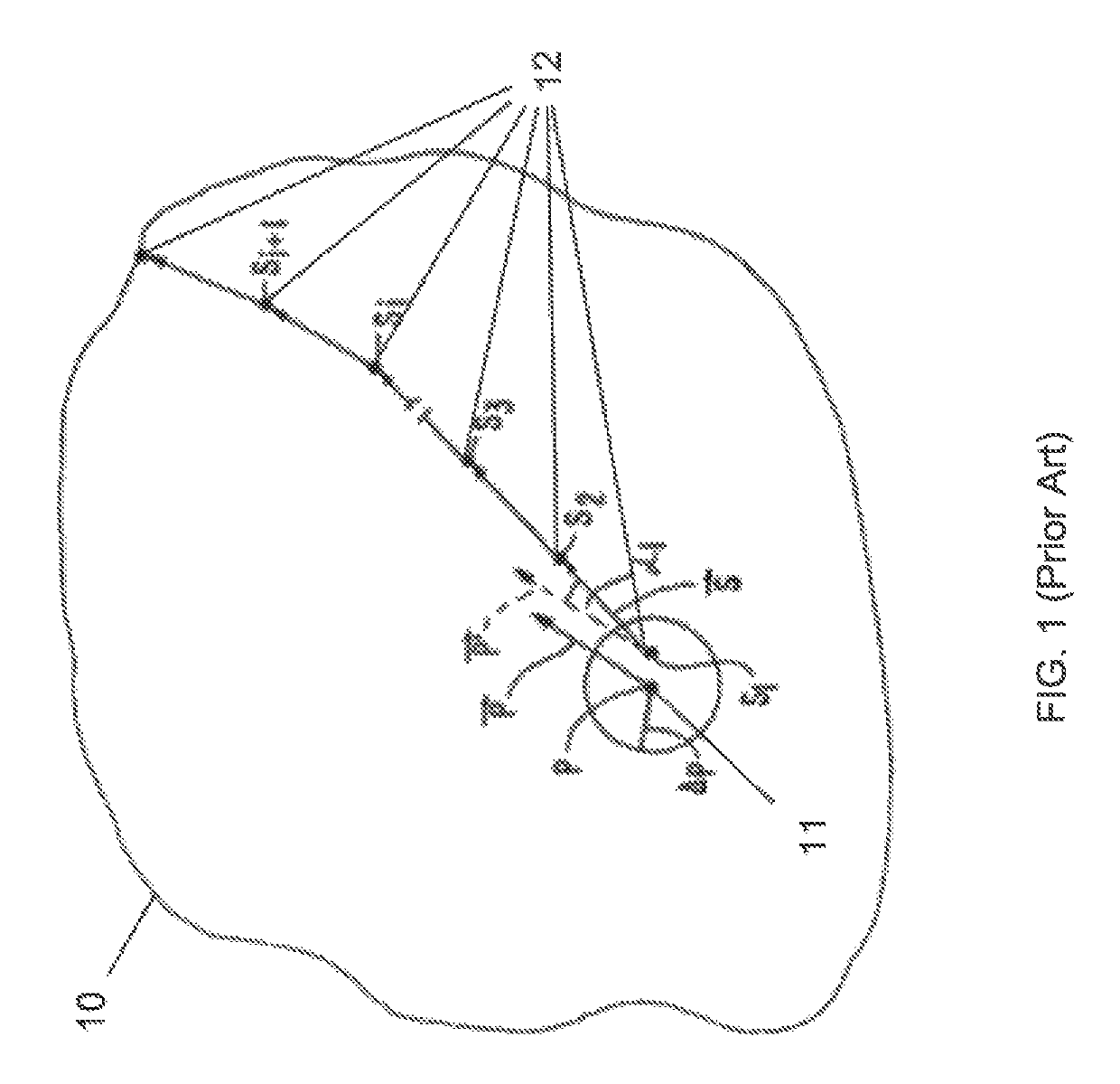
RELATED APPLICATION[0001]This application claims the benefit of U.S. Provisional Patent Application Ser. No. 62 / 324,734, entitled System, Method, and Mechanism for Analyzing Spatial Field Efficiency and Determining Optimal Machine Working Direction(s) of Travel within a Field Boundary, filed on Apr. 19, 2016, the contents of which are incorporated herein by reference in their entirety for all purposes.BACKGROUNDTechnical Field[0002]This invention relates to a machine control system for determining an optimal machine working direction(s) of travel within a field boundary for machine guidance, and more specifically, to a system and method that generates a simulated travel path estimate to calculate spatial field efficiency over a plurality of splayed initial working directions of travel.Background Information[0003]The problem of determining the most efficient route to take when farming a field is one that has challenged generations of farmers. Modern machine control promises to solve ...

Claims


Application Information

Patent Timeline
Patent Type & Authority Patents(United States)
IPC IPC(8): G05D1/02G05D1/00A01B5/04A01B79/00G01C21/20A01B69/04A01B69/00
CPCA01B69/008G01C21/20G05D1/0219G05D1/0217G05D2201/0201
Inventor WOLTERS, DUSTIN J.WATKINS, BRIAN H.THOMPSON, MICHAEL J.
Owner CROPZILLA SOFTWARE INC
Learn More