
Valve device for a motor vehicle

a valve device and motor vehicle technology, applied in the direction of valve arrangements, machines/engines, engine controllers, etc., to achieve the effect of simple production and advantageous cost

Active Publication Date: 2019-07-23
VITESCO TECH GERMANY GMBH
View PDF32 Cites 0 Cited by
  • Summary
  • Abstract
  • Description
  • Claims
  • Application Information

AI Technical Summary

Benefits of technology

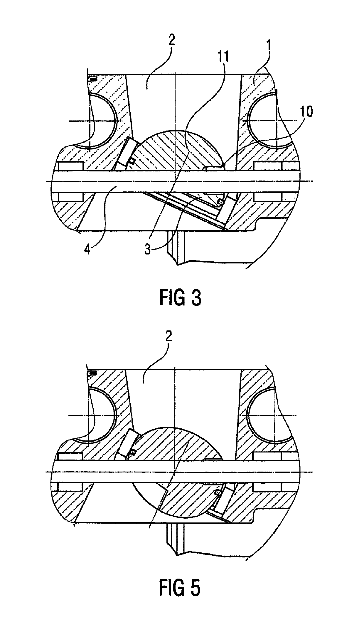
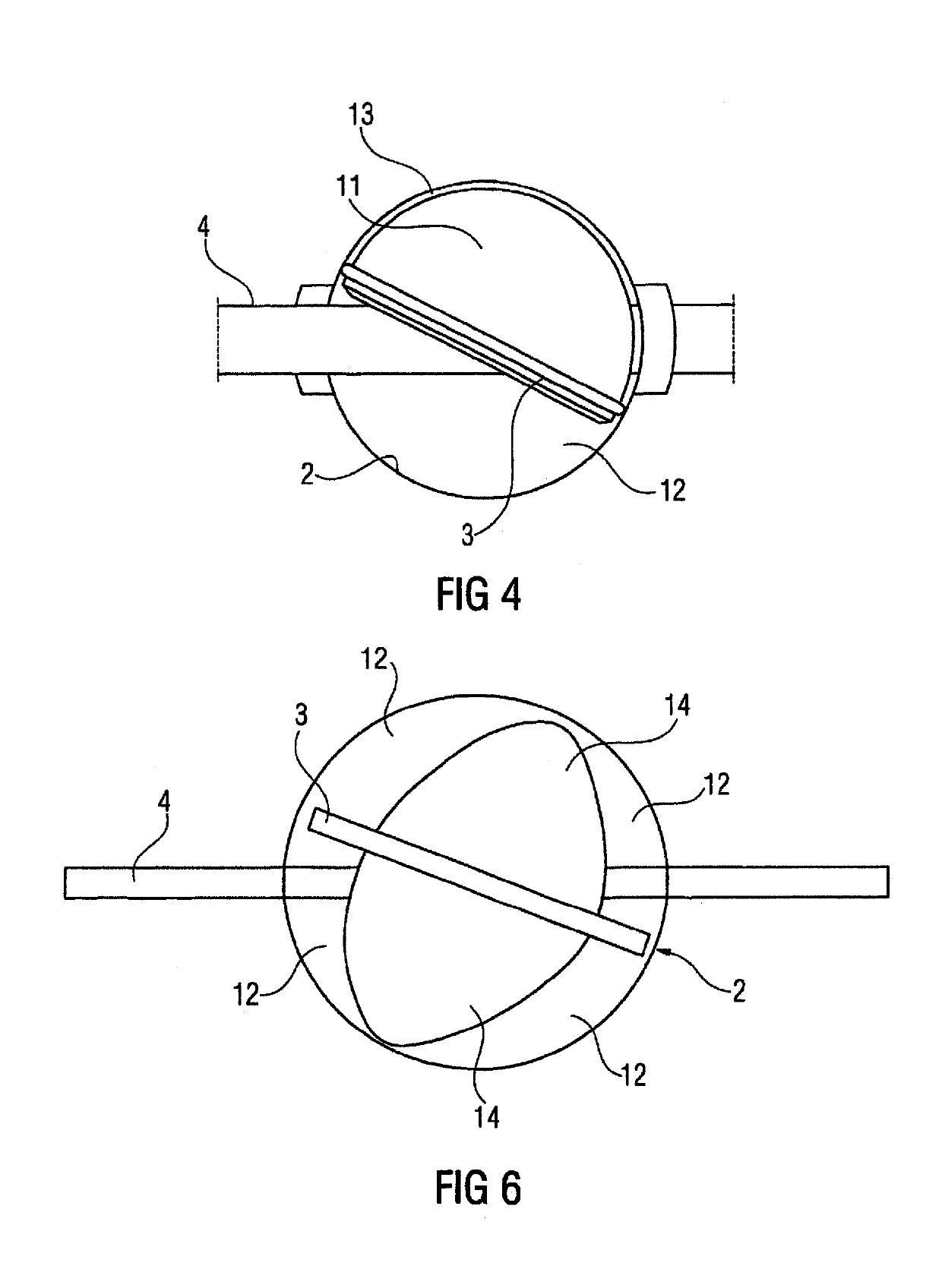
[0008]The spherical elevation has the effect that a smaller flow cross section is available in the flow channel for the maximum mass flow when the flap is fully open than would be the case with a disk-shaped flap. The use of the flap according to the invention thus allows the use of a housing with a flow channel, the cross section of which is designed for a maximum mass flow or the flow cross section. Adapting the valve device to the respective maximum mass flow is made possible by the use of a flap since the flow cross section is reduced by careful design of the at least one spherical elevation. Thus, all that is necessary is to adapt the flap according to the desired requirements, while the remainder of the valve device can be used without alteration for all applications. In this context, all flaps of disk-shaped design, apart from the regions in which the shaft passes through the, flap are regarded as disk-shaped flaps. The regions in which the shaft passes through the flap must therefore necessarily deviate from the flat disk-shaped design since these regions are often used to secure the flap on the shaft.
[0020]The individual flap components can be connected by welding, adhesive bonding or screwing. It has an advantageous effect on costs if the flap components are simultaneously connected to the shaft by welding or screwing, for example.

Problems solved by technology

The disadvantage here is that different valve devices with correspondingly designed housings and the flow channels, in particular flow cross sections, running therein are necessary for different requirements.

Method used


Image

  • Valve device for a motor vehicle
  • Valve device for a motor vehicle
  • Valve device for a motor vehicle

Examples


Embodiment Construction

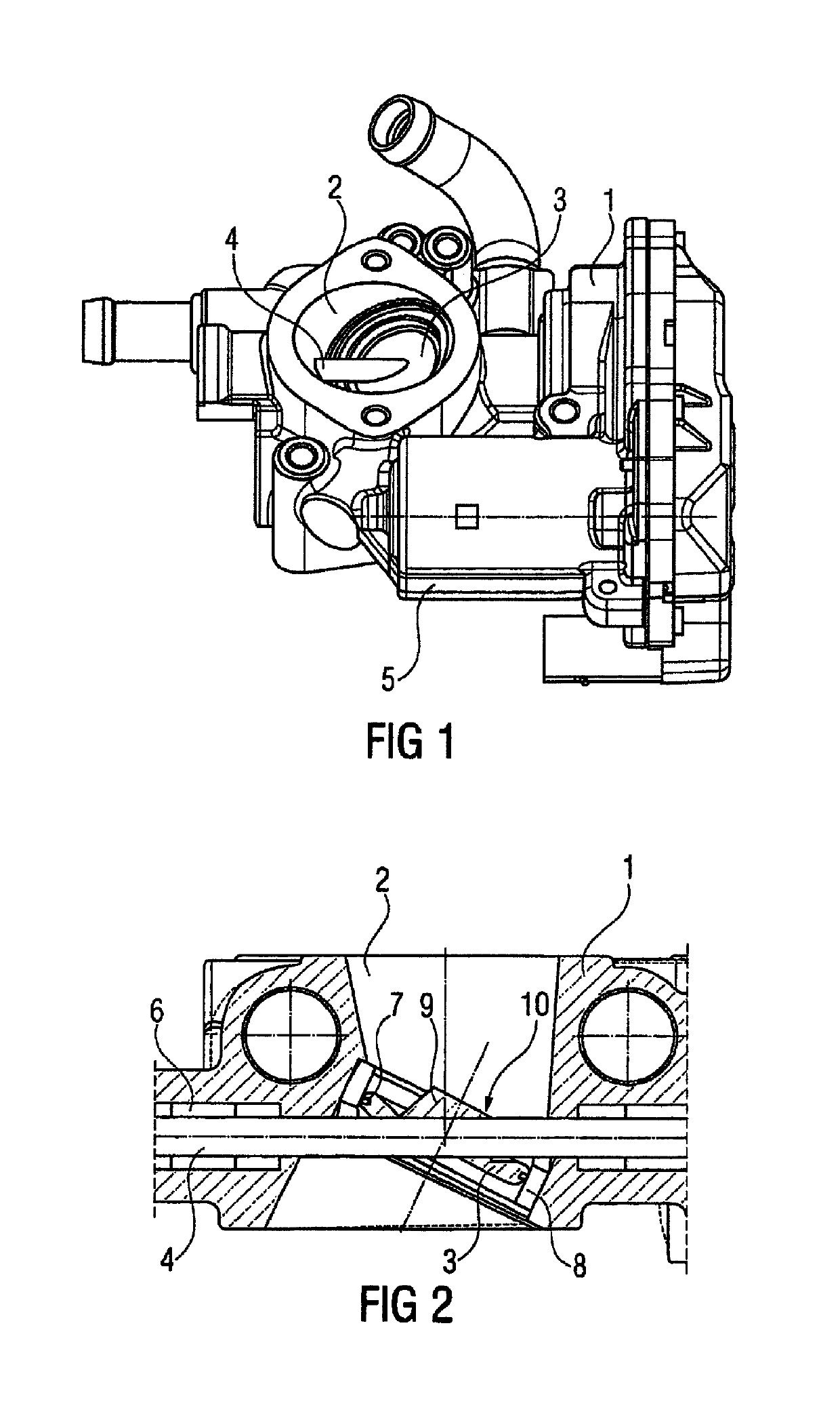
[0026]FIG. 1 shows a valve device according to the prior art, having a housing 1 and a flow channel 2, which is located in the housing and in which a disk-shaped flap 3 is arranged. The flap 3 is connected securely to a shaft 4, and the shaft 4 is rotatably supported in the housing 1. The shaft 4 is driven by an electric motor 5 arranged in the housing, wherein a transmission is arranged between the shaft 4 and the electric motor 5.

[0027]FIG. 2 shows the region of the flow channel 2 according to FIG. 1 in section. The shaft 4 is rotatably supported in the housing 1 by bushes 6. The disk-shaped flap 3 is secured on the shaft 4 for conjoint rotation by a welded joint. In the illustration shown, the flap 3 fully closes the flow channel 2. Sealing is effected by a sealing ring 7, which is arranged in a groove in the flap 3. The sealing ring 7 seals the flow channel relative to the inner wall of a ring 8 inserted into the flow channel 2. When the shaft 4 is rotated, the flap 3 opens, exp...


PUM


Abstract

A valve device for a motor vehicle includes a housing, a flow channel located in the housing, and a flap arranged in the flow channel for closing the flow channel. The flap has regions in which a shaft penetrating the flap is fastened, and the shaft is rotatably supported in the housing. The flap has a spherical elevation at least on one side.

Description

CROSS-REFERENCE TO RELATED APPLICATIONS[0001]This is a U.S. national stage of application No. PCT / EP2012 / 076209, filed on 19 Dec. 2012, which claims priority to the German Application No. 10 2012 200 054.2, filed 3 Jan 2012, the content of both incorporated herein by reference.BACKGROUND OF THE INVENTION[0002]1. Field of the Invention[0003]The present invention relates to a valve device for a motor vehicle, having a housing, a flow channel located in the housing, and a flap arranged in the flow channel for closing the flow channel, wherein the flap is fastened on a shaft, and the shaft is rotatably supported in the housing.[0004]2. Related Art[0005]Valve devices of this kind are used as throttle assemblies, for example, and have long been known. By the rotatably supported flap, it is possible to fully close the flow channel or, by rotating the flap through 90°, to open the flow channel in such a way that a maximum mass flow occurs. Accordingly, the valve device is designed for the m...

Claims


Application Information

Patent Timeline
Patent Type & Authority Patents(United States)
IPC IPC(8): F02D9/08F16K1/22F02D9/10
CPCF02D9/08F02D9/101F16K1/222F02D9/1025F02D9/107
Inventor KOHLEN, PETERMOBS, STEFANVON WILLICH, JOACHIM
Owner VITESCO TECH GERMANY GMBH
Learn More