
Multi-fiber optical connector

a fiber optic connector and fiber technology, applied in the field of multi-fiber optical connectors, can solve the problems of low workability at the time of connecting each fiber and the need for a certain amount of fiber length, and achieve the effects of high workability, simple structure and convenient assembly

Inactive Publication Date: 2019-07-16
NAMIKI PRECISION JEWEL CO LTD
View PDF20 Cites 3 Cited by
  • Summary
  • Abstract
  • Description
  • Claims
  • Application Information

AI Technical Summary

Benefits of technology

The connector can be easily assembled with improved positioning accuracy and reduced loss during connection, as fibers can be elastically connected without precise polishing, and the structure enhances reliability by protecting against foreign matter.

Problems solved by technology

In such a transmission medium in the related art, each of the fibers is connected by fusion splice, and while respective fiber cores to be connected can be coaxially fixed with high accuracy, there may be disadvantages in which workability at the time of connecting each fiber is low and a length of a fiber is needed to have a certain amount of margin because of a method thereof.

Method used


Image

  • Multi-fiber optical connector
  • Multi-fiber optical connector
  • Multi-fiber optical connector

Examples


Embodiment Construction

[0027]In the following, the best embodiment of the present invention will be described using FIGS. 1, 2, 3, and 4.

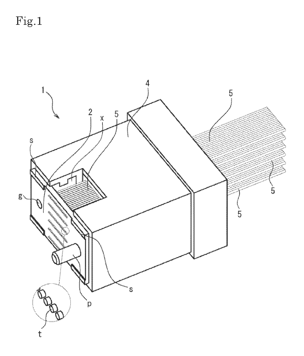
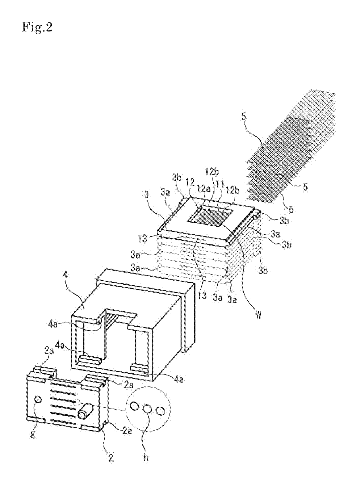
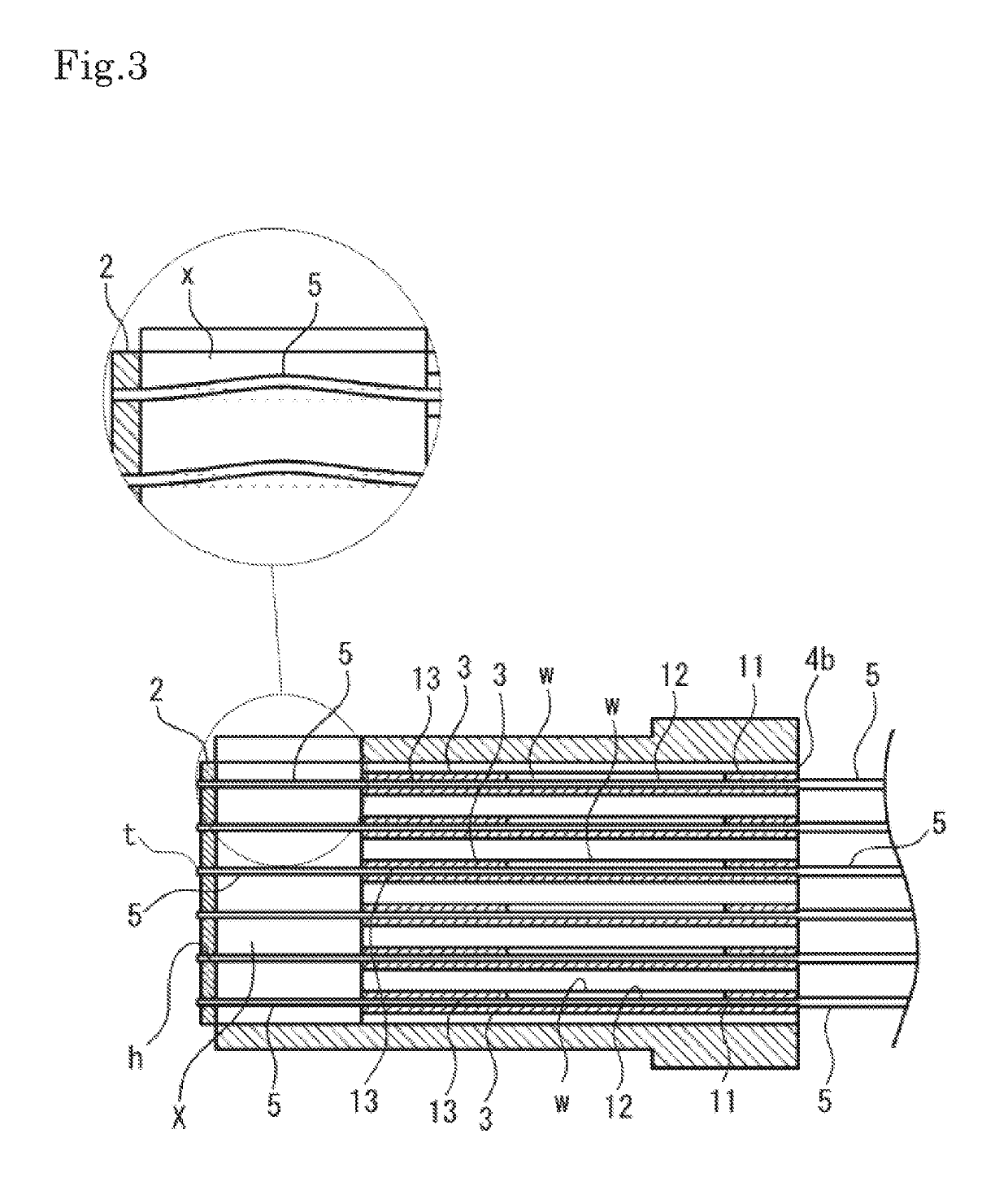
[0028]FIG. 1 is a perspective view of an entire multi-fiber optical connector used in the present embodiment, FIG. 2 is an exploded perspective view of the multi-fiber optical connector, FIG. 3 is a side cross-sectional explanatory view illustrating a structure inside the connector when the multi-fiber optical connector is connected, and FIG. 4 is an exploded perspective view of the multi-fiber optical connector, respectively. Note that illustration of a rear end portion of a fiber is omitted in the drawings.

[0029]As illustrated in FIGS. 1, 2, and 3, a multi-fiber optical connector 1 according to the present embodiment includes a plate-shaped guide 2, a fiber guide 3, and a holder 4, and has a structure in which a tip portion t of a fiber 5 inserted into a penetration hole h provided inside the plate-shaped guide 2 from a rear end side of the multi-fiber optical connecto...


PUM


Abstract

Provided is a multi-fiber optical connector which can be easily assembled by having a simple structure and provides high workability at the time of connection.Since a plate-shaped guide 2 adapted to move a fiber is provided on an end surface and a gap x is provided on a rear surface of the plate-shaped guide 2, achieved is a structure in which each of fibers 5 is mutually moved in an optical axis direction along a penetration hole h provided at the plate-shaped guide 2 at the time of connecting connectors. Consequently, the respective fibers 5 which can be elastically connected independently from each other can be collectively connected at the time of connecting the connectors, and furthermore, positioning accuracy between the respective fibers 5 can be improved when the connector is used as a multi-fiber optical connector 1.

Description

RELATED APPLICATIONS[0001]The present application is National Phase of International Application No. PCT / JP2016 / 002118 filed Apr. 20, 2016, and claims priority from Japanese Application No. 2015-086169, filed Apr. 20, 2015, the disclosure of which is hereby incorporated by reference herein in its entirety.TECHNICAL FIELD[0002]The present invention relates to a multi-fiber optical connector attached to one end of an optical cable and adapted to collectively connect a plurality of fibers.BACKGROUND ART[0003]Presently, a transmission medium in which a plurality of optical fibers such as a tape core wire and an optical cable are bundled are widely used in the field of optical communication. In such a transmission medium in the related art, each of the fibers is connected by fusion splice, and while respective fiber cores to be connected can be coaxially fixed with high accuracy, there may be disadvantages in which workability at the time of connecting each fiber is low and a length of a...

Claims


Application Information

Patent Timeline
Patent Type & Authority Patents(United States)
IPC IPC(8): G02B6/36G02B6/38
CPCG02B6/3885G02B6/3839G02B6/3809G02B6/38
Inventor ABUMI, MASAHIROIKEGAI, KAZUAKIODA, NOBUHIKOHAYASHI, TAKEHIRO
Owner NAMIKI PRECISION JEWEL CO LTD
Learn More