Pedicle screw with large-diameter bone thread

a technology of pedicle screw and bone thread, which is applied in the direction of internal osteosythesis, fasteners, and osteosythesis devices, can solve the problems of limited and determined maximum bone screw diameter, and achieve the effect of reducing or minimizing the notch effect and constant core diameter

Active Publication Date: 2019-07-02
AESCULAP AG
View PDF9 Cites 13 Cited by
  • Summary
  • Abstract
  • Description
  • Claims
  • Application Information

AI Technical Summary

Benefits of technology

[0011]By means of the differently large diameters of the distal connection thread portion (small / little) and of the proximal connection thread portion (large / wide) the following contrary effects are achieved: On the one hand, the small distal connection thread portion reduces the notch effect acting on the bone. This enables the screw to counteract high tensile strength / “pull-out strength”. On the other hand, the wide proximal connection thread portion allows for increased moment loading of the screw which permits an increased adjusting moment.
[0012]In order to be able to ensure safe stable and permanent connection of the bone screw and the shank head element, a particular length of the connection thread is required. According to the idea underlying the invention, the connection thread between the bone screw and the shank head element of known pedicle screw systems is quasi subdivided into plural thread portions. The thread diameters, especially nominal diameters, thereof are different from each other. Proximal connection thread portions have a larger diameter (nominal diameter) than distal connection thread portions. Hence it can be stated that the diameters of the connection thread portions are decreasing from the proximal end to the distal end. Another effect brought about in this way resides in the fact that the wall thickness of the bone screw varies stepwise in the zone of the connection threads, namely in plural steps smaller as compared to prior art (where at the run-out of the connection thread a relatively great change of cross-section having a corresponding notch effect occurs). In this way, on the one hand the notch effect occurring at the end of the connection thread, especially at the distal thread run-out, can be minimized as compared to prior art. On the other hand, the notch effect is spread to a larger portion of the bone screw in the longitudinal direction, viz. to the entire length of the connection thread, by providing plural connection thread run-outs, viz. at each connection thread portion. In total, the invention helps to substantially reduce the loads acting on and the tensions introduced to the bone screw in the zone of the connection thread as compared to prior art while maintaining the thread length. The pedicle screw system according to the invention therefore can be configured to have a (substantially) cylindrical bone thread core while having an identical outer diameter, an identical screwing strength, identical unscrewing strength and identical biomechanical fatigue strength.
[0016]It is of particular advantage when the shank head element includes a stop on which a stop surface of the bone screw, especially the proximal end face thereof, abuts when the shank head element and the bone screw are completely screwed to each other via the respective connection threads thereof. The multi-thread employed according to the invention causes, jointly with the stop, the bone screw to be subjected to compressive stress in the entire zone between the distal connection thread and the stop. Said compressive stress ensures higher capacity as regards an absorption of biomechanical forces acting on the bone screw. The shank head element and the bone screw may abut on the stop to be especially sealing with each other so that the connection thread will not get stained and is easy to clean.
[0018]One embodiment of the invention is characterized in that the central opening of the bone screw includes a proximal non-threaded portion and a distal non-threaded portion between which the distal connection thread portion and the proximal connection thread portion are arranged. Said non-threaded portions may advantageously be used as positioning aids and facilitate setting the pedicle screw by an operating surgeon.
[0020]It is of particular advantage when the distal non-threaded portion has a smaller diameter than the distal connection thread portion and the proximal non-threaded portion has a larger diameter than the proximal connection thread portion. This helps to reduce or minimize the notch effect due to the change of cross-sections.
[0021]Another embodiment of the invention is characterized in that the bone thread includes a cylindrical or substantially or approximately cylindrical threaded core having a substantially constant core diameter. Said bone thread safeguards tight hold of the bone screw within the bone and uniform load introduction over the entire length of the bone thread into the bone material. Another embodiment of the invention is characterized in that the thread depth of the bone thread is constant in the area of the connection thread.

Problems solved by technology

Especially with a polyaxial pedicle screw having a large bone screw diameter it may be a problem that the maximum bone screw diameter possible is determined and limited by the geometry and the dimensions of the receiving sleeve.
A possible problem of said multipart pedicle screw in certain cases may be the fact that the bone thread has to be very flat and tapered in the area of the screwing of the bone screw and the shank head element, viz. in the area of the connection screwing so as to ensure sufficient stability of the bone screw and to be able to reduce or prevent the probability of a rupture of the bone screw due to the thin wall between the bone thread and the connection thread fostered by the high notch effects thereof.

Method used


Image

  • Pedicle screw with large-diameter bone thread

Examples


Embodiment Construction

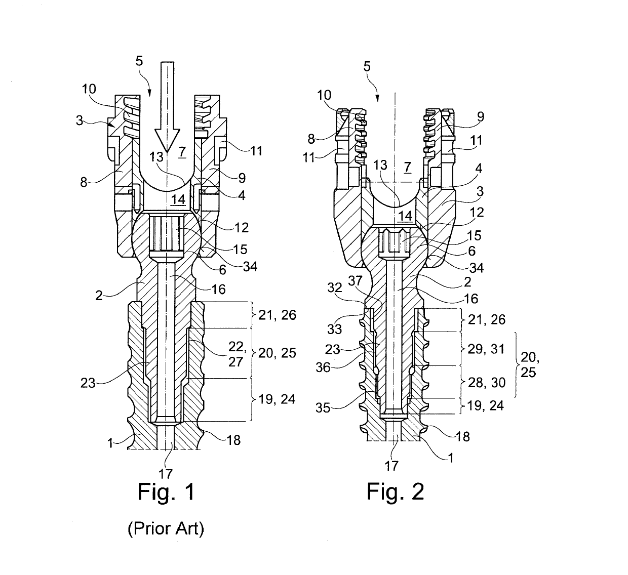
[0028]Both pedicle screw systems, viz. the one according to prior art shown in FIG. 1 as well as the one according to the invention shown in FIG. 2, comprise a pedicle screw 1, a shank head element 2, a receiving sleeve 4, also referred to as tulip, and a clamping die 4.

[0029]The receiving sleeve 3 is a separate component and is movably arranged on the shank head element 2 so that a polyaxial pedicle screw system is formed in which the receiving sleeve 3 can be angularly positioned, especially rotated and / or pivoted, relative to the bone screw 1 and to the shank head element 2. The receiving sleeve has a substantially cylindrical basic form including a through-hole 5 in the longitudinal direction. The distal end zone of the through-hole 5 is formed to be inwardly tapering in the form of a spherical segment in the radial direction and constitutes a ball seat 34 for a ball head 6 of the shank head element 2. At the proximal end, in the receiving sleeve 3 a receiving chamber 7 for a lo...


PUM


Abstract

A pedicle screw system includes a receiving sleeve for a longitudinal support, a bone screw and a shank head element. The bone screw has a bone thread configured as an outer thread and a connection thread configured as an inner thread. The shank head element has at the proximal end a head on which the receiving sleeve is mounted and, at the distal end, a connection thread configured as an outer thread screwed into the connection thread of the bone screw. The connection threads are configured as multi-threads, each with a distal connection thread portion and a proximal connection thread portion. The distal connection thread portion and the proximal connection thread portion have an identical thread pitch. The distal connection thread portion has a smaller diameter than the proximal connection thread portion.

Description

RELATED APPLICATIONS[0001]This application is the United States national phase entry of International Application No. PCT / EP2017 / 061232, filed May 10, 2017, which claims the benefit of priority of German Application No. 10 2016 108 972.9, filed May 13, 2016. The contents of International Application No. PCT / EP2017 / 061232 and German Application No. 10 2016 108 972.9 are incorporated by reference herein in their entireties.FIELD[0002]The present invention relates to a pedicle screw system comprising a receiving sleeve for a longitudinal support, a bone screw and a shank head element, with the bone screw having a bone thread configured as an external thread and a connection thread configured as an internal thread, wherein the shank head element at the proximal end (from the surgeon's viewpoint) includes a head on which the receiving sleeve is supported and wherein the shank head element at the distal end (from the surgeon's viewpoint) includes a connection thread configured as an exter...

Claims


Application Information

Patent Timeline
Patent Type & Authority Patents(United States)
IPC IPC(8): A61B17/70A61B17/86
CPCA61B17/8685A61B17/8625A61B17/7032A61B17/7037
Inventor LINDNER, STEPHAN
Owner AESCULAP AG
Why Eureka
Try Eureka