Lid assembly with ring to control flow

a technology of spout and ring, which is applied in the field of spout with a ring, can solve the problems of more complicated manufacturing process, more expensive to add this piece for manufacturers, and complicated construction, and achieve the effect of improving the sanitary use of the spou

Inactive Publication Date: 2019-07-02
THERMOS LLC
View PDF6 Cites 1 Cited by
  • Summary
  • Abstract
  • Description
  • Claims
  • Application Information

AI Technical Summary

Benefits of technology

[0006]A beverage container system is described. The beverage container may include a lid assembly for a beverage container and, optionally, a beverage container as well. The lid assembly includes an outer ring, a spout, and a lid main body. The outer ring is rotated by the user to drive the spout toward and away from the lid main body. The movement of the spout opens and closes—or, in other words, blocks or unblocks—openings or fluidic passages of the lid assembly that are formed in the lid main body. The lid main body may include or be comprised of a base member that generally remains stationary relative to the beverage container. Both the spout and the outer ring may move relative to the base member. In some aspects, the base member includes both an inner member and an outer member, while in other aspects, the base member is a single piece construction. The lid assembly controls the flow of the liquid from the container without the need to directly touch the spout, which improves the sanitary use of the spout since user drinks the liquid directly from the spout.
[0007]The lid assembly includes a spout, which may be retractable and extendable by rotation of the outer ring to control the amount of the fluid passing through the spout. The lid assembly requires a minimal number of parts to retract and extend the spout, provides infinite or variable flow control, and relieves the concerns of hygiene because direct touch of the spout can be avoided. In addition, the openings created by the lid assembly are configured to be generally small enough that fruit, ice, and other relatively chunky additives will generally not pass through, thereby permitting the use of such additives in the container to treat / flavor the beverage without the user actually consuming them.
[0009]In one aspect, the present application overcomes problems inherent in the prior art and provides a lid assembly including an outer ring removably engaged to a spout having a seal. The seal is configured to minimize unintended leakage of liquid between the spout and the outer ring. The spout is operatively engaged to a base member having a base side wall, such as a bore, and a bottom surface that defines openings. The base side wall and the bottom surface may be integrally or piecemeal connected via one or more flanges. The space between the bottom of the base side wall, the outer circumference of the bottom surface, and the side edges of the flanges defines openings through which the liquid may flow. The beverage container system of the present application also provides a method for controlling the flow of liquid and additives, either infinitely or according to pre-settings.
[0011]In another aspect, a lid assembly for a beverage container is configured to achieve an open position to permit a user to drink liquid therethrough and to achieve a closed position that generally limits the liquid passage therethrough. The lid assembly includes a spout having a mouth portion and a lower circular end positioned generally opposite the mouth portion, wherein the mouth portion is configured to receive the user's lips. The lid assembly includes a base member having a bottom surface, a base side wall, and flanges, wherein the bottom surface, the base side wall, and the flanges define openings that permit passage of liquid when the lid assembly is in the open position and wherein the lower circular end of the spout meets with the bottom surface to block the passage of liquid through the openings when the lid assembly is in the closed position. The lid assembly includes an outer ring configured to permit the user to maneuver the spout and the base member relative to each other to achieve the open position and the closed position, such that the user does not have to directly touch the spout to achieve either position, which decreases contamination of the mouth portion of the spout. The openings are sized and shaped to generally block the passage of relatively chunky additives therethrough, even when the lid assembly is in the open position.
[0015]Another aspect of the present application provides a lid assembly with a spout that controls the flow of liquid through the spout infinitely or according to a presetting.

Problems solved by technology

Some flow-managing spouts, such as retractable spouts, require the user to use their fingers to pull out or push in the spout portion that the mouth will touch, which creates concerns about hygiene.
Other flow-managing spouts require a separate cap piece to stop the flow and to keep the spout clean, which is an extra step for the users to remove and properly position the cap and often more expensive to add this piece for the manufacturers.
Still other flow-managing spouts require a more complicated construction possibly including a coiled spring actuating a screw cap and an air venting tube.
These retractable spouts in the prior art generally require many parts, require more complicated manufacturing processes, and may not promote hygienic use of the products.
However, these extra parts—the cage or strainer or second container—add additional pieces to be cleaned and maintained by the user and also may add to manufacturing costs.

Method used


Image

  • Lid assembly with ring to control flow
  • Lid assembly with ring to control flow
  • Lid assembly with ring to control flow

Examples


Embodiment Construction

[0044]For purposes of this application, any terms that describe relative position (e.g., “upper”, “middle”“lower”, “outer”, “inner”, “above”, “below”, “bottom”, “top”, etc.) refer to an embodiment of the invention as illustrated, but those terms do not limit the orientation in which the embodiments can be used.

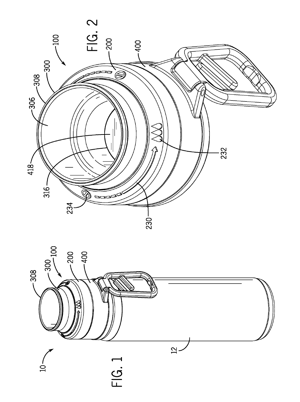
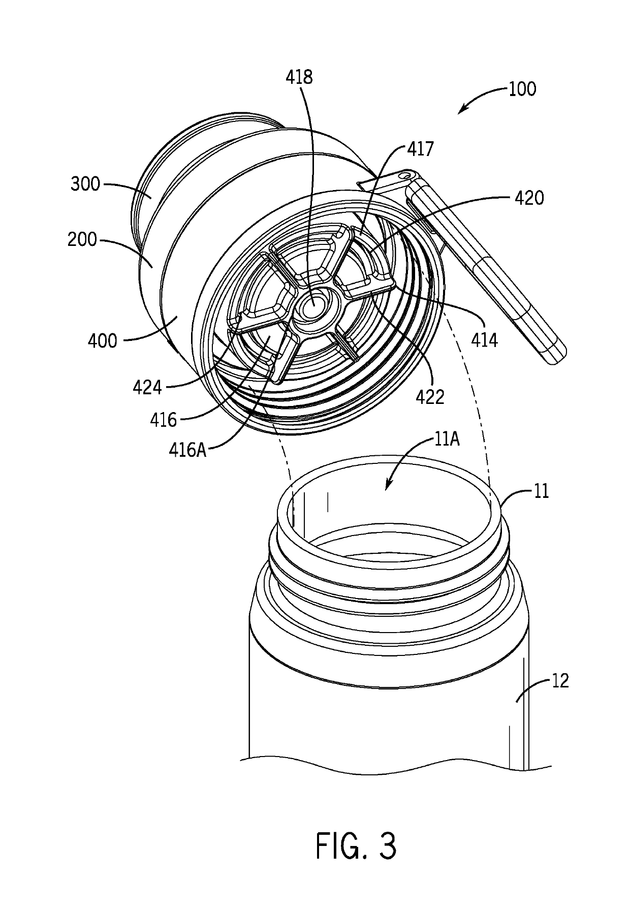
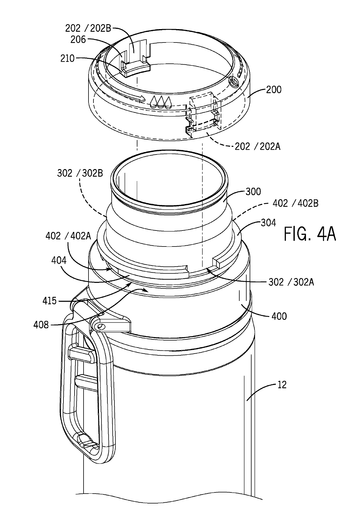
[0045]In FIG. 1 through FIG. 10, a numerical symbol “10” represents, as a whole, a beverage container system of the present disclosure. The beverage container system 10 includes a container main body 12 and a lid assembly 100. The container main body 12 includes a container mouth 11 defining a container opening 11A. The lid assembly 100 includes an outer ring 200, a spout 300, and a base member 400. The lid assembly 100 opens and closes the container main body 12 to prevent or allow the flow of liquid from the container main body 12. The lid assembly 100 engages to the container main body 12 via a threaded engagement, snap-fit connection, frictional connection, compression con...


PUM


Abstract

A lid assembly for a beverage container is described. The lid assembly includes an outer ring, a spout, and a base member. The outer ring is rotated by the user to drive the spout toward the base member. The movement of the spout opens and closes openings or fluidic passages of the lid assembly.

Description

CROSS REFERENCE TO RELATED APPLICATION[0001]This application claims the benefit of U.S. Provisional Patent Application 62 / 144,881 filed Apr. 8, 2015, which is hereby incorporated by reference.FIELD OF INVENTION[0002]The present invention relates to a lid assembly with a ring for a beverage container, with the ring to control the flow of a liquid through the lid assembly.DESCRIPTION OF RELATED ART[0003]A user often wishes to manage the flow of a liquid out of a container to avoid spilling or otherwise pouring out or drinking more liquid than intended. For example, if a beverage is warm or hot, the user may only want a small sip to test the temperature or otherwise avoid burning their mouth, lips, or tongue. There are many different types of spouts to facilitate managing a flow of a liquid out of a container. Some flow-managing spouts, such as retractable spouts, require the user to use their fingers to pull out or push in the spout portion that the mouth will touch, which creates con...

Claims


Application Information

Patent Timeline
Patent Type & Authority Patents(United States)
IPC IPC(8): A47G19/22A45F3/18
CPCA45F3/18A47G19/2272
Inventor LANE, MARVIN
Owner THERMOS LLC
Why Eureka
Try Eureka