
Shore protection infrastructure equipped with means for recovering energy from wave motion

a technology of energy recovery and infrastructure, applied in the direction of piers, machines/engines, groynes, etc., can solve the problems of difficulty in establishing a useful mean undulation, inconvenient operation, and inability to meet the needs of the current system for using the energy deriving from the recovery of wave motion

Active Publication Date: 2019-06-11
DOCK POWER SRL
View PDF31 Cites 1 Cited by
  • Summary
  • Abstract
  • Description
  • Claims
  • Application Information

AI Technical Summary

Benefits of technology

This patent is about a system that can capture and store energy from the movement of water in lakes or sea basins using floats connected to a crank mechanism. The system aims to address the irregular frequency of wave motion that can affect the energy recovery process. The technical effect is a more reliable and consistent energy recovery system.

Problems solved by technology

The use of these prior art systems for the use of wave motion has highlighted certain problems, the main one of which is represented by efficiency or performance limitations due to the low frequency of the wave motion, when, on the contrary, high speeds are preferable for the operation of electricity generators.
More specifically, the current systems for using energy deriving from the recovery of the wave motion are subject to the sudden changes, often considerable, to the waves due in some cases to the variation of the tides or to the different weather conditions or in other cases to the different intensity of the passage of boats.
These variations of the flow of the wave motion determine an irregularity of the thrusts exerted on the traditional energy recovery means, creating difficulty in establishing a mean undulation useful for the conversion of the sussultatory motion into constant motion of the crank mechanism.

Method used


Image

  • Shore protection infrastructure equipped with means for recovering energy from wave motion
  • Shore protection infrastructure equipped with means for recovering energy from wave motion
  • Shore protection infrastructure equipped with means for recovering energy from wave motion

Examples


Embodiment Construction

[0017]The aim of this invention is to provide a system for the recovery and storage of energy received from wave motion of lakes or sea water basins through the use of floats connected to a crank mechanism thereby creating a condition which is able to eliminate or at least reduce the above-mentioned drawbacks relating to the irregular frequency of the wave motion.

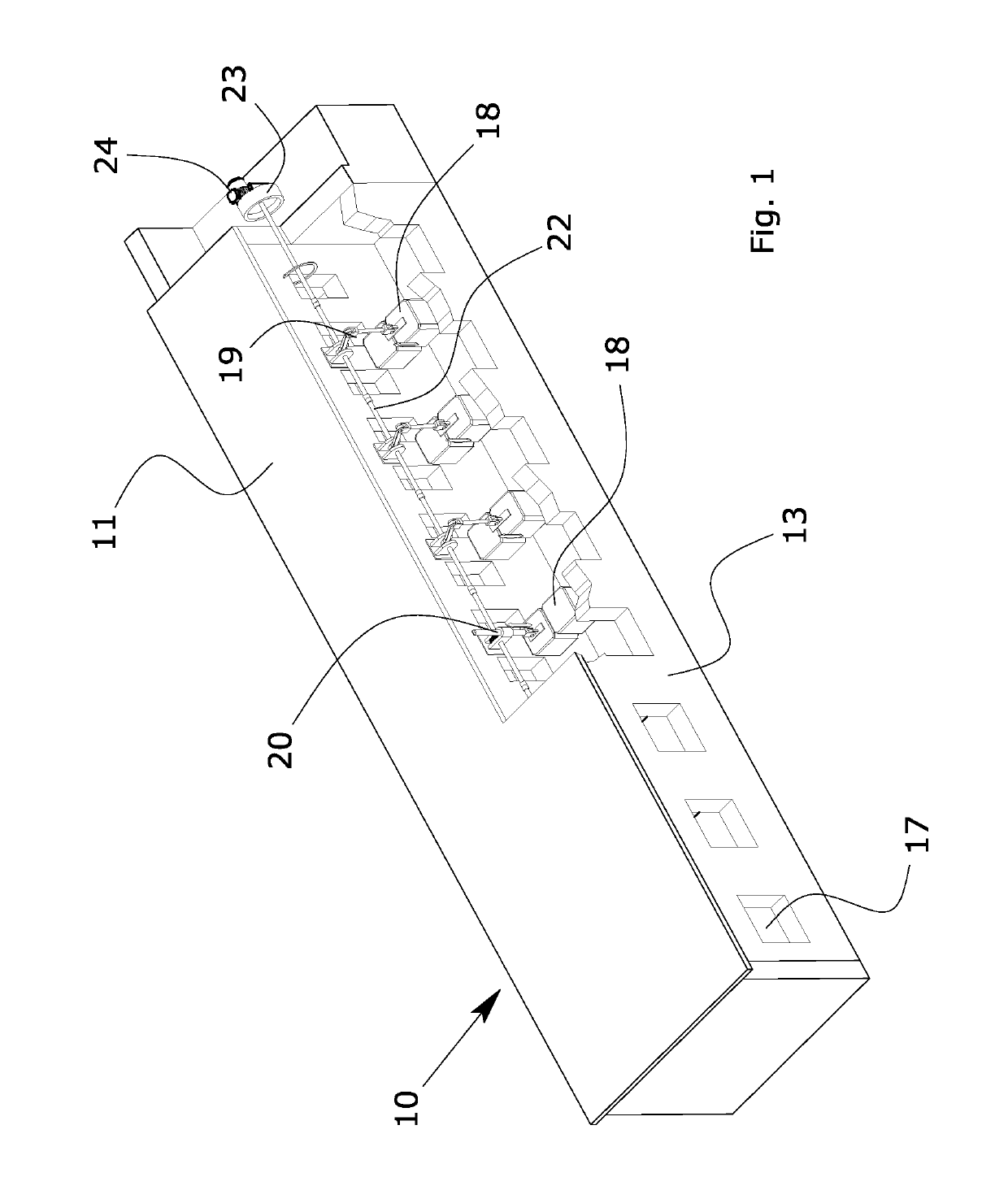
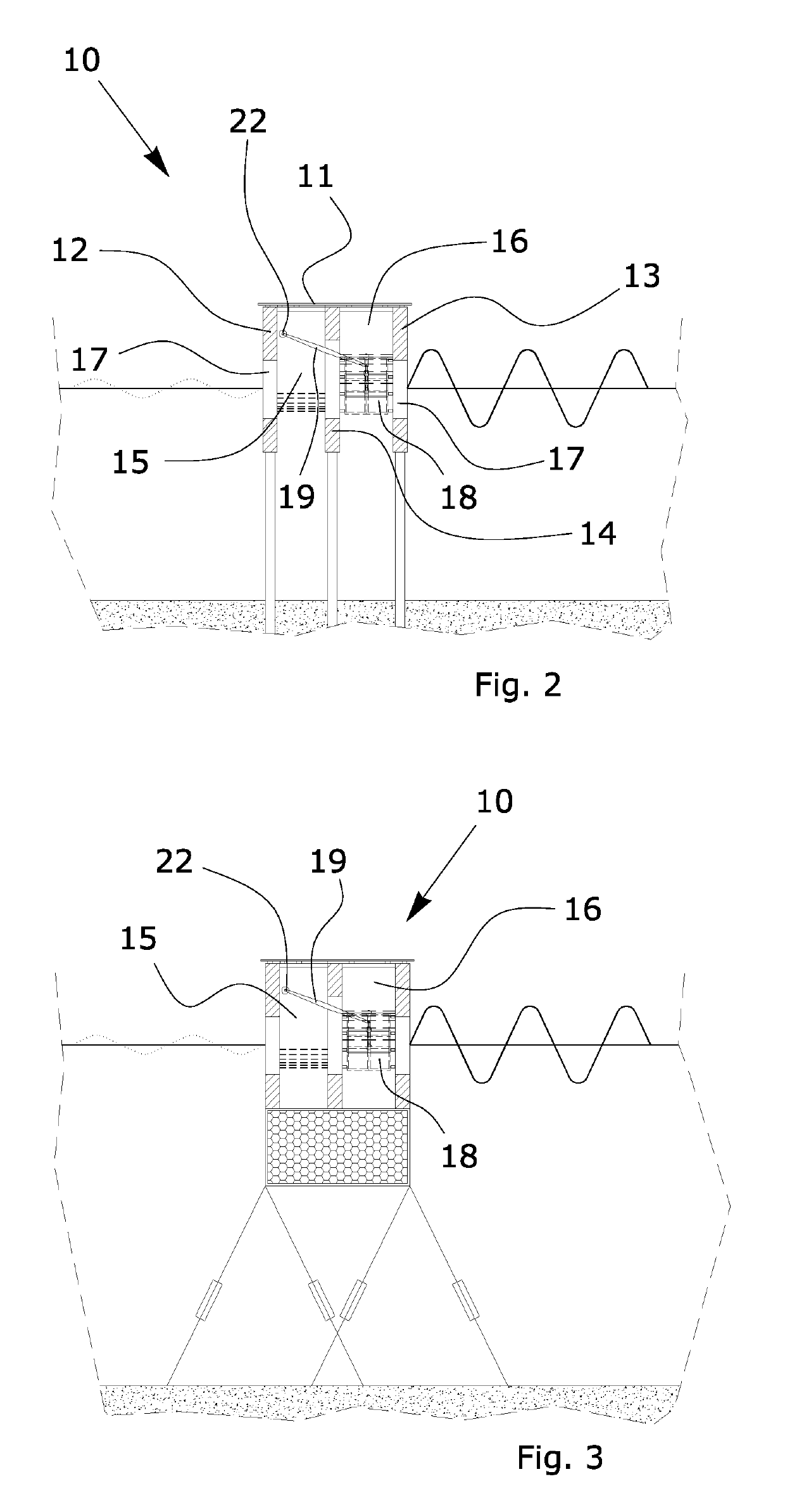
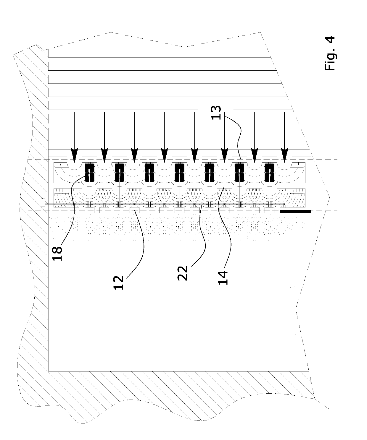
[0018]The invention aims in particular to provide a system for the recovery and storage of energy which derives from the wave motion, through the combination between a floating or fixed quay, jetty, pier or mooring and an energy recovery system, which allows the vertical oscillation of the wave motion to be exploited, linking it with a plurality of floats which transfer the motion to a shared rotation shaft.

[0019]This is achieved by means of a system for the recovery and storage of energy received from wave motion, the features of which are described in the main claim.

[0020]The dependent claims of the solution according to ...


PUM


Abstract

Described is an infrastructure for recovering and storing energy received from wave motion of lakes or sea water basins, comprising a floating or fixed quay, jetty or pier (10) substantially consisting of a platform (11) in the lower part of which are fixed walls (12, 13, 14) equipped with openings (17) for the passage of the wave motion towards inner chambers (15, 16), wherein the inner chambers comprise units for recovering the energy from the wave motion, comprising floats (18) connected by kinematic means (19, 20) to at least one transmission shaft (22) in turn associated with a unit (24) which transforms the mechanical energy into directly usable or storable electricity, the kinematic means (19, 20) being capable of converting the sussultatory motion of the floats (18) into rotary motion of the shaft (22) allowing the recovery of electricity from the relative transformation unit (24).

Description

TECHNICAL FIELD[0001]This invention relates to a system for the recovery and storage of energy received from wave motion of lakes or sea water basins associated with an infrastructure for protecting the shore of the breakwater quay type.[0002]Substantially, the system according to the invention recovers the energy produced by the wave motion of the water present in lakes or sea water basins, during the vertical oscillation of the surface, through the use of one or more floating units, each connected by a crank mechanism, or a rack-type kinematic means, or to a free wheel which rotates a shaft connected in turn to a handwheel associated with a unit for the recovery and storage of the mechanical energy, the means being positioned inside a quay representing a breakwater barrier.[0003]According to the invention, the forces produced by the thrusts of the wave motion attenuated by the breakwater barrier on which the energy recovery unit is positioned allow the sussultatory movement of sui...

Claims


Application Information

Patent Timeline
Patent Type & Authority Patents(United States)
IPC IPC(8): E02B9/08E02B3/06F03B13/14F03B13/18
CPCE02B3/064E02B3/06E02B3/062E02B9/08F03B13/186F03B13/1815F03B13/14Y02E10/38F05B2240/40Y02A10/15Y02A10/11Y02E10/30
Inventor LORENZI, DAVIDELUMINARI, LORENZO
Owner DOCK POWER SRL
Learn More