Optically pumped atomic magnetometer and magnetic sensing method
a technology of atomic magnetometer and magnetic sensing method, which is applied in the direction of measuring using magnetic resonance, etc., can solve the problem of increasing the size of the apparatus
- Summary
- Abstract
- Description
- Claims
- Application Information
AI Technical Summary
Benefits of technology
Problems solved by technology
Method used
Image
Examples
first embodiment
[0030]An optically pumped atomic magnetometer and a magnetic sensing method according to a first embodiment of the present invention will be described with reference to FIGS. 1 to 4.
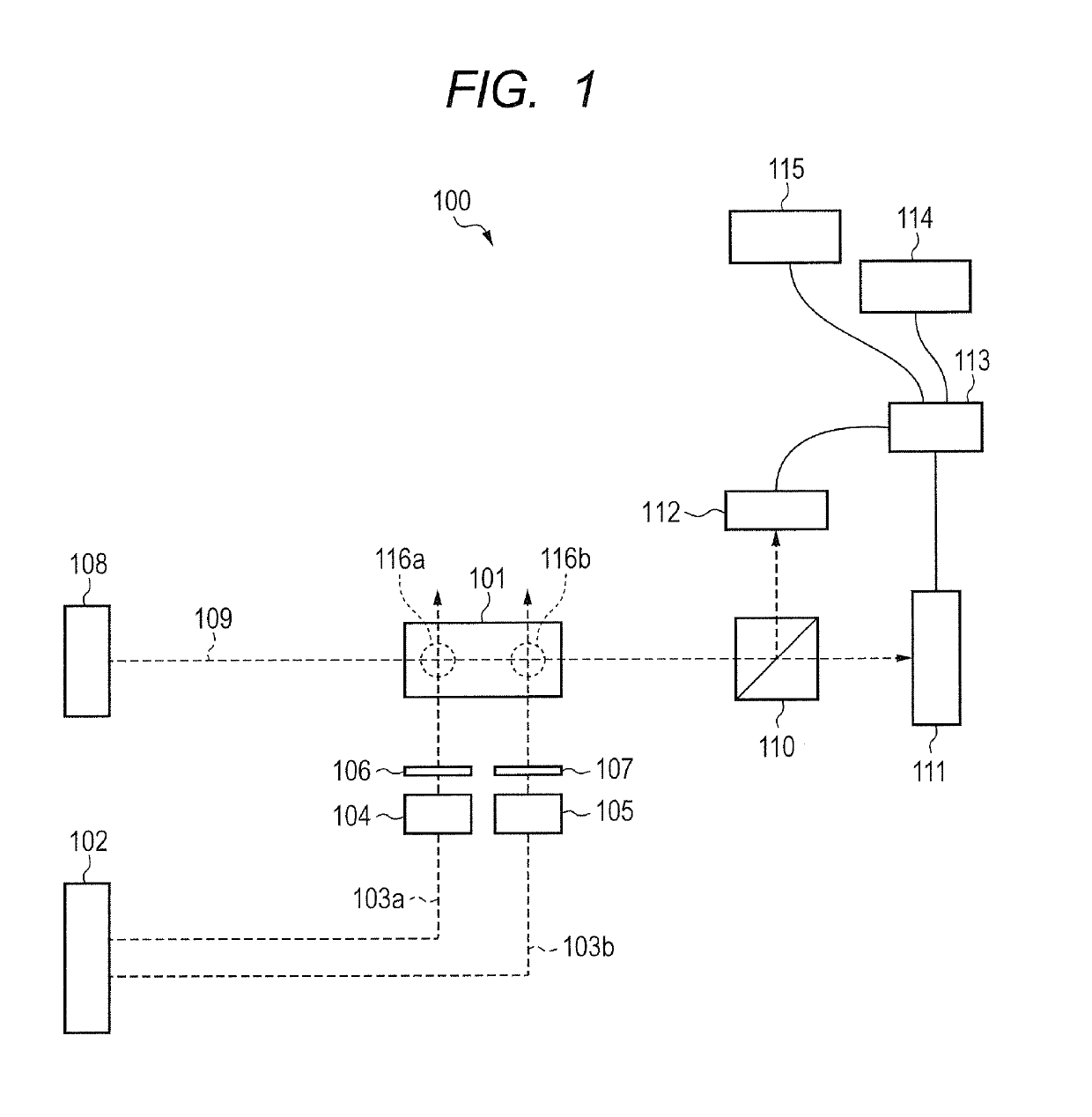
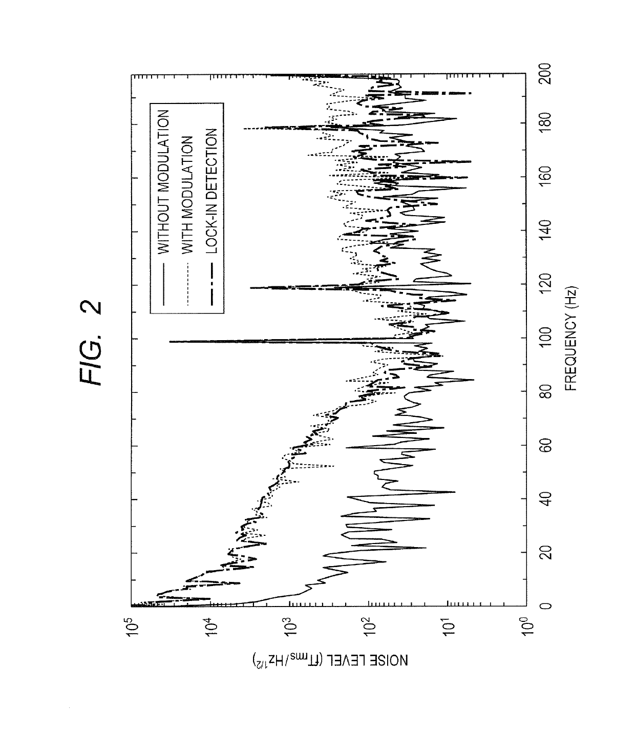
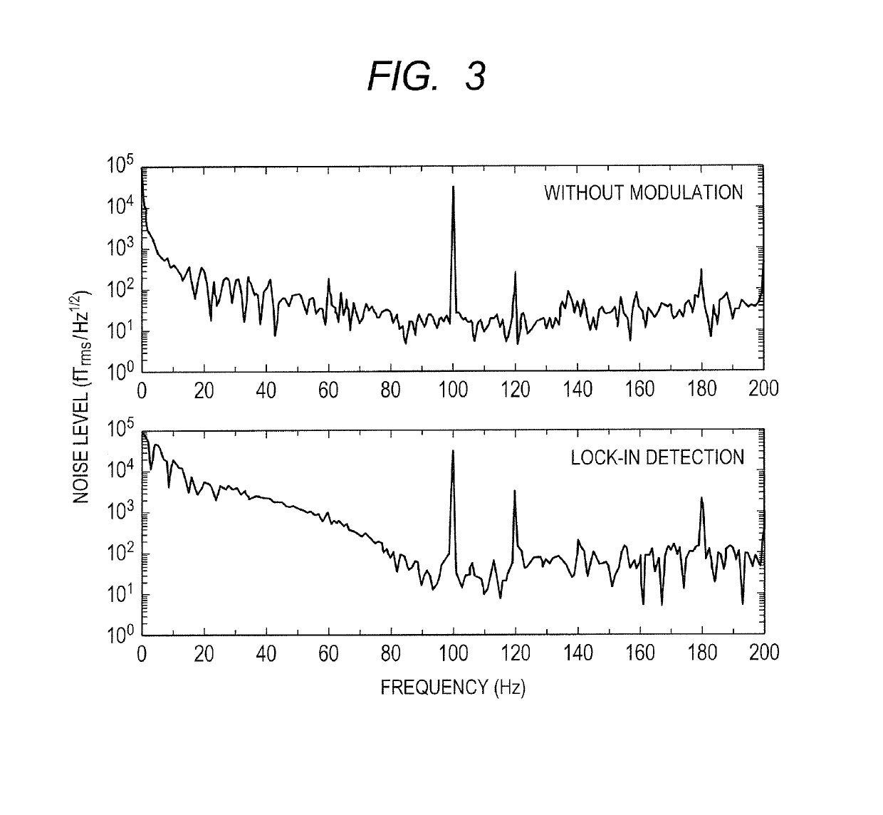
[0031]FIG. 1 is a schematic diagram illustrating a configuration of the optically pumped atomic magnetometer according to the present embodiment. FIGS. 2 to 4 are diagrams illustrating an example of results of measurement using the optically pumped atomic magnetometer according to the present embodiment.
[0032]First, a schematic configuration of the optically pumped atomic magnetometer according to the present embodiment will be described with reference to FIG. 1.
[0033]As illustrated in FIG. 1, an optically pumped atomic magnetometer 100 according to the present embodiment includes a cell 101, a pump beam optical system 102, optical modulators 104 and 105, phase retarders 106 and 107, and a probe beam optical system 108. The optically pumped atomic magnetometer 100 also includes a polarization separation ...
second embodiment
[0065]An optically pumped atomic magnetometer and a magnetic sensing method according to a second embodiment of the present invention will be described with reference to FIGS. 5 to 6D. The same constituent elements as in the optically pumped atomic magnetometer according to the first embodiment illustrated in FIGS. 1 to 4 are expressed by the same names, and the description will be omitted or simplified. The description of the same constituent elements in the embodiments can be applied to each other within a range not contrary to the configurations specific to the embodiments.
[0066]FIG. 5 is a schematic diagram illustrating a configuration of the optically pumped atomic magnetometer according to the present embodiment. FIGS. 6A to 6D are schematic diagrams illustrating an example of a modulation method of pump beam.
[0067]First, a schematic configuration of the optically pumped atomic magnetometer according to the present embodiment will be described with reference to FIG. 5.
[0068]As...
third embodiment
[0122]An optically pumped atomic magnetometer and a magnetic sensing method according to a third embodiment of the present invention will be described with reference to FIG. 5 and FIGS. 7A to 7C. The same constituent elements as in the optically pumped atomic magnetometer according to the first and second embodiments illustrated in FIGS. 1 to 6D are expressed by the same names, and the description will be omitted or simplified. The description of the same constituent elements in the embodiments can be applied to each other within a range not contrary to the configurations specific to the embodiments.
[0123]First, a schematic configuration of the optically pumped atomic magnetometer according to the present embodiment will be described with reference to FIG. 5.
[0124]The optically pumped atomic magnetometer according to the present embodiment is the same as the optically pumped atomic magnetometer according to the second embodiment illustrated in FIG. 5, except that the demodulators 22...
PUM
 Abstract
Description
Claims
Application Information
 - R&D
- Intellectual Property
- Life Sciences
- Materials
- Tech Scout
- Unparalleled Data Quality
- Higher Quality Content
- 60% Fewer Hallucinations
Browse by: Latest US Patents, China's latest patents, Technical Efficacy Thesaurus, Application Domain, Technology Topic, Popular Technical Reports.
© 2025 PatSnap. All rights reserved.Legal|Privacy policy|Modern Slavery Act Transparency Statement|Sitemap|About US| Contact US: help@patsnap.com


