Medical injection device

a technology of injection device and injection needle, which is applied in the direction of intravenous device, medical syringe, injection needle, etc., can solve the problems of unfavorable port rotation of the container relative to the port, and the inability to connect the portion in the region of the plug-in connection

Active Publication Date: 2019-05-07
RAUMEDIC AG
View PDF58 Cites 0 Cited by
  • Summary
  • Abstract
  • Description
  • Claims
  • Application Information

AI Technical Summary

Benefits of technology

[0006]In order to remove the protective cap from the injection cannula, a user may either grasp the anti-rotation device or the protective cap. When the protective cap is being screwed off in order to remove the protective cap from the port and connection portion, an unwanted rotation of the container relative to the port and connection portion in the region of the plug-in connection is then not possible. This prevents an unwanted release of the plug-in connection when the protective cap is being screwed off, thus ensuring that an interior of the container remains sterile. The plug-in connection may be a tapered connection. The plug-in connection may be a Luer-Lock connection. The plug-in connection may be configured in a rotationally-symmetric manner in such a way as to allow for a rotation of the port and connection portion relative to the near-cannula end of the container about a cannula axis. The plug-in connection may be provided with at least one snap-in portion such that the connection is secured by means of a positive fit.
[0007]An axial covering of the plug-in connection by the anti-rotation protection prevents access to the plug-in connection from outside, which also helps to prevent an unwanted release of the plug-in connection.
[0011]A carrier ring configuration of the positive-fit adapter formed in one piece with the at least one positive-fit latch, wherein the carrier ring is push-fittable onto the port and connection portion and is snap-locked therewith, results in a particularly stable design and an effective anti-rotation protection. Alternatively, the positive-fit adapter may be configured in the shape of a letter C such that it is push-fittable over the port and connection portion from the side and is in particular snap-lockable therewith. This facilitates an assembly of the positive-fit adapter.
[0012]An embodiment for holding down the at least one positive-fit latch by means of at least one inner axial rib which interacts with a counter hold-down means at the positive-fit adapter results in a particularly secure anti-rotation protection of the positive-fit adapter relative to the port and connection portion. The hold-down counter means may be formed by an outer axial rib of the positive-fit adapter.
[0013]A multi-component injection-molding design of the at least one component of the anti-rotation protection increases the possibilities of manufacturing the components of the anti-puncture device. The multi-component injection-molded part may be configured as a two-component injection-molded part or as an injection-molded part comprising more than two components, for instance three components, four components, five components or even more components. Softer plastic materials may be combined with harder plastic materials. Softer plastic materials may for instance be used for a grip portion of the anti-puncture device or for formed parts abutting against counter components in order to compensate for a play therebetween and / or in order to produce or increase a frictional fit between the respective formed part and the respective counter component.
[0016]A multi-component injection-molding design of the positive-fit member and the positive-fit member carrier body allows the at least one positive-fit member, which may be configured as an axial rib, to be made of a material that is softer than that of the positive-fit member carrier body, with the result that a frictional fit between the positive-fit members and the inner port and connection portion is improved. This results in an improved anti-rotation protection of the positive-fit adapter relative to the port and convection portion.

Problems solved by technology

When the protective cap is being screwed off in order to remove the protective cap from the port and connection portion, an unwanted rotation of the container relative to the port and connection portion in the region of the plug-in connection is then not possible.

Method used


Image

  • Medical injection device
  • Medical injection device
  • Medical injection device

Examples


Embodiment Construction

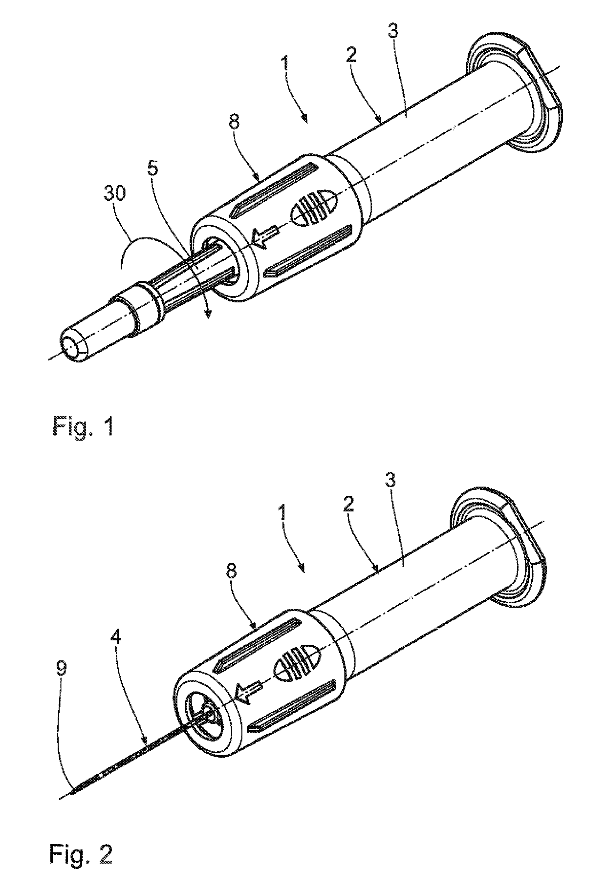
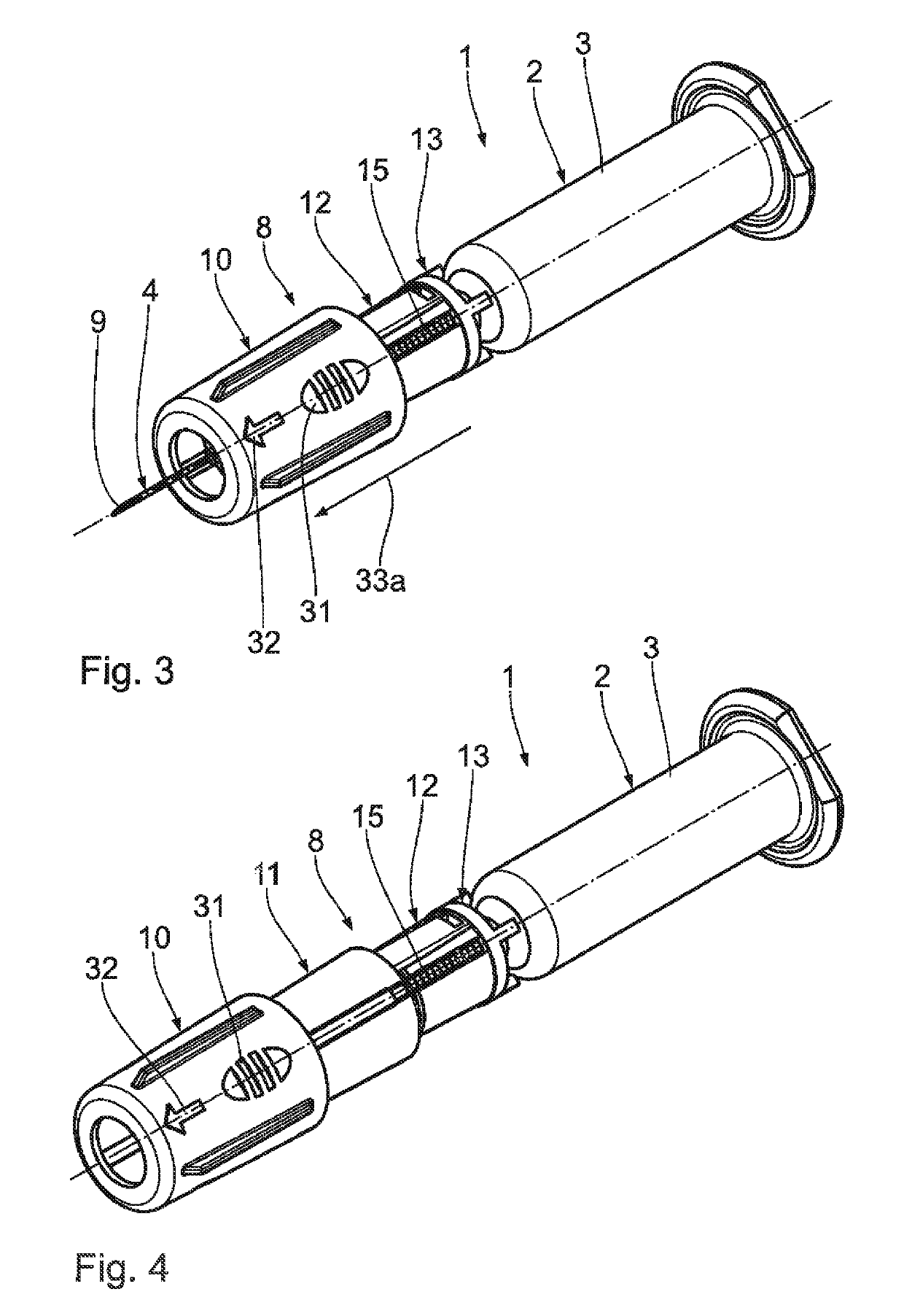
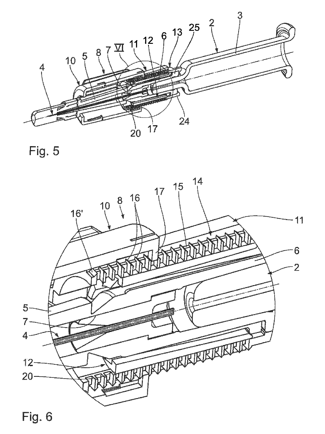
[0044]FIGS. 1 to 11 show an embodiment of a medical injection device 1. The injection device 1 has an injection unit 2. This injection unit 2 includes a container 3 for the medium to be injected. The container 3 may be configured as a syringe container for receiving a syringe plunger which is not shown in the drawing. The injection unit 2 further includes an injection cannula 4 which is visible in FIG. 2 and which is covered in FIG. 1 by an original protective cap 5. Upon delivery of the injection device 1 according to FIG. 1, the original protective cap 5 is fitted onto the injection cannula 4 and axially snap-locked with a near-cannula end of the container 3. For injection of the medium, the injection cannula 4 communicates with the container 3 via a near-cannula port and connection portion 6 of the container 3 which is visible in the sectional view according to FIG. 5. The port and connection portion 6 is also referred to as opening and connection portion 6. The opening and conne...


PUM


Abstract

A medical injection device has an injection unit and an anti-rotation device. Said anti-rotation device is non-rotationally connected to a port and connection portion of the injection device so as to surround the outside thereof in the manner of a sleeve. As a result, an intuitively usable and operationally safe injection device is obtained. When a protective cap for an injection cannula of the injection unit is being removed from the port and connection portion, an unwanted rotation of the port and connection portion relative to the container about components of a plug-in connection arranged therebetween is safely prevented.

Description

CROSS-REFERENCE TO RELATED APPLICATIONS[0001]This application claims the priority of German patent application, Serial No. DE 10 2013 214 442.3, filed Jul. 24, 2013, pursuant to 35 U.S.C. 119(a)-(d), the content of which is incorporated herein by reference in its entirety as if fully set forth herein.FIELD OF THE INVENTION[0002]The invention relates to a medical injection device comprising an injection unit.BACKGROUND OF THE INVENTION[0003]Medical injection devices are known from EP 460 914 B1, from EP 707 860 B1, from U.S. Pat. No. 4,838,871, from EP 692 271 B1, from U.S. Pat. No. 4,944,397, from U.S. Pat. No. 4,982,842, from U.S. Pat. No. 5,232,455, from U.S. Pat. No. 5,139,489, from U.S. Pat. No. 5,154,285, from U.S. Pat. No. 5,277,311, from U.S. Pat. No. 5,232,454, from U.S. Pat. No. 5,312,367, from U.S. Pat. No. 5,342,322, from U.S. Pat. No. 5,423,765, from U.S. Pat. No. 5,643,219, from WO 1991 / 009639 A2, from EP 862 920 B1, from EP 885 621 B1, from EP 1 525 016 B1, from EP 1 5...

Claims


Application Information

Patent Timeline
Patent Type & Authority Patents(United States)
IPC IPC(8): A61M5/32A61M5/31
CPCA61M5/326A61M5/3202A61M5/3216A61M5/3245A61M2005/3217A61M2005/312A61M2005/3118
Inventor JAKOB, THOMASMAAG, SEBASTIANFESTEL, TOBIASBRAUN, THOMASSKAPER, FRANK
Owner RAUMEDIC AG
Why Eureka
Try Eureka