
Flexible ring structure for jewelry

a flexible, ring technology, applied in the field of jewelry, can solve the problems of not being useful, reducing the customer experience, and not always desirable design choice of oversized bracelets or bangles that can be slipped over the hand

Active Publication Date: 2019-04-30
PECK KEVEN
View PDF3 Cites 13 Cited by
  • Summary
  • Abstract
  • Description
  • Claims
  • Application Information

AI Technical Summary

Benefits of technology

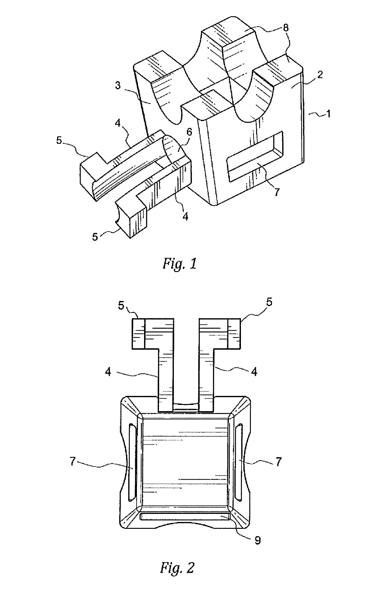
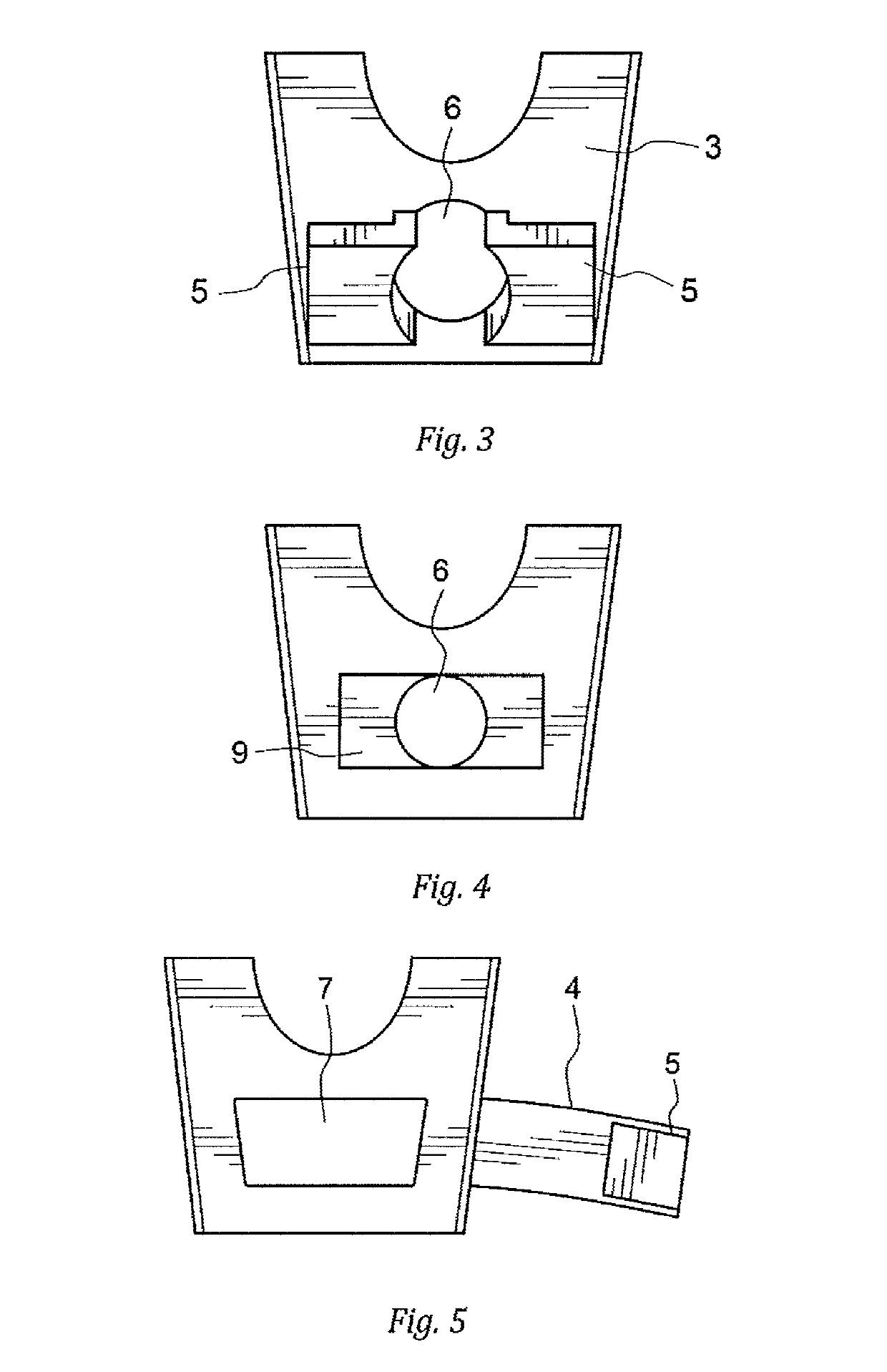
The invention is a decorative ring made up of linked trapezoidal prisms that can flex to fit on a wearer's finger or wrist. The prisms are non-rigidly linked and can move relative to each other. The band has a tensioned core spring that keeps the prisms pressed together, but when the band is unstressed, the prisms can move freely. This allows the ring to fit snugly on a wearer's finger or wrist. When an external force is applied, the band will flex to fit the wearer's finger or wrist better. Overall, the invention provides a flexible and comfortable alternative to traditional rings.

Problems solved by technology

This can diminish a customer experience who continues to wear an improperly fitting ring or is unwilling to have it resized.
Such solutions are not useful when the appearance of a continuous circular band is desired.
The design choice of an oversized bracelet or bangle that can be slipped over the hand is not always desirable.

Method used


Image

  • Flexible ring structure for jewelry
  • Flexible ring structure for jewelry
  • Flexible ring structure for jewelry

Examples


first embodiment

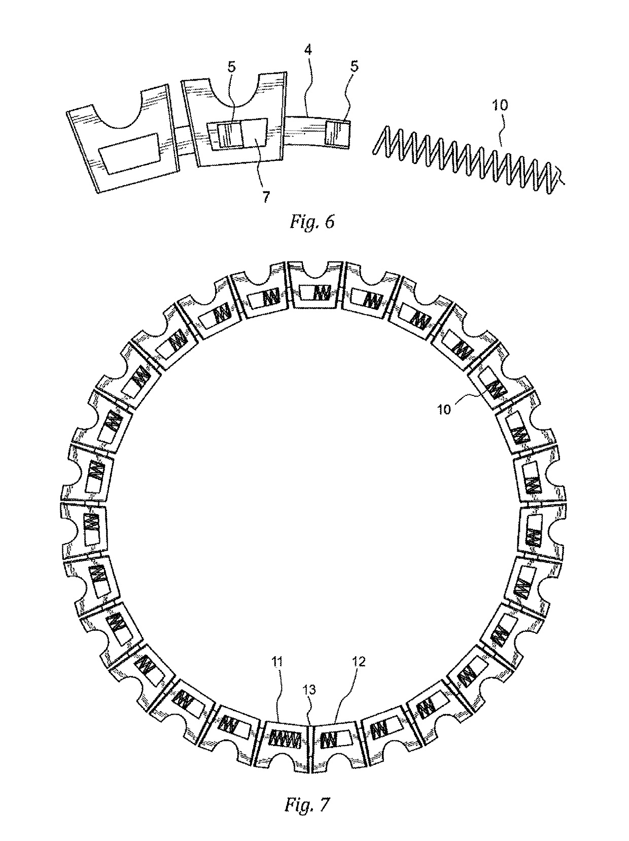
[0016]In a first embodiment, the ends of the tensioned spring are affixed to the ends of the chain. The tension of the spring then biases the ends of the chain toward each other, thereby holding the prisms in contact with one another. To form a bracelet, the ends of the chain are brought together and fastened to one another. For prisms made from metal, welding or soldering are the preferred methods of affixing the ends of the chain to one another. In a preferred method of manufacture, the prongs are removed from one end of the chain prior to soldering the ends together, in order to simplify assembly.

second embodiment

[0017]In a second embodiment, the spring is passed through the interior passage of the chain, and is stretched out sufficiently to permit the ends of the spring to be fastened together. This can be done, for example, by soldering, by the use of a clip or similar device, by bending the ends of the springs into mutually engaged hooks, or by soldering the two ends if the spring into the interior of a single prism. The tension of the spring biases the circular chain inward, toward a smaller circumference, thereby holding the prisms in contact with one another.

[0018]The trapezoidal shape of the prisms causes the chain, when compressed by the tensioned spring, to adopt a curved shape. The angle of the sloped (front and rear) sides of the prisms determines the number of prisms that define a full circle, and it will generally be preferred that this is the number of prisms used in the chain. For a desired number n of prisms, the front and rear sides of each prism should subtend an angle θ=36...


PUM


Abstract

The invention provides a flexible ring structure made of loosely-linked prisms, which together define an interior channel. A tensioned spring runs through the length of the channel. The ring, which gives the appearance of a solid and rigid circular structure, can be compressed so as to conform to the cross-section of the finger or hand, and springs back to a circular shape when released. The invention makes it possible to wear an Eternity Ring or a bracelet of smaller diameter than could otherwise be put on the wrist.

Description

REFERENCE TO PRIOR APPLICATION[0001]This application claims priority of U.S. Provisional patent application Ser. No. 62 / 510,319, filed May 21, 2017, the contents of which are incorporated herein by reference.FIELD OF THE INVENTION[0002]The invention is in the field of jewelry, more specifically rings, bracelets, necklaces, and other decorative bands.BACKGROUND[0003]Typical rings are of a fixed structure and must be sized. This can diminish a customer experience who continues to wear an improperly fitting ring or is unwilling to have it resized. The solid ring has the attractive feature of presenting a richer and more solid appearance. For round structures used in bracelets, they must be left with an opening, or be provided with a hinge and a latch, in order to be put over the wrist. Such solutions are not useful when the appearance of a continuous circular band is desired. The design choice of an oversized bracelet or bangle that can be slipped over the hand is not always desirable....

Claims


Application Information

Patent Timeline
Patent Type & Authority Patents(United States)
IPC IPC(8): A44C5/08A44C9/02
CPCA44C5/08A44C9/02A44C11/007
Inventor PECK, KEVEN
Owner PECK KEVEN
Learn More