
Method for operating a wind farm

a wind farm and wind power technology, applied in the direction of machines/engines, electric generator control, greenhouse gas reduction, etc., can solve the problems of unfavorable resumption of the operation of such a wind turbine, unfavorable idling operation mode, and high cost of drawing such electrical power from the grid, so as to improve the protection against corrosion, the effect of reducing the idling operation mode and increasing the recorded atmospheric humidity

Active Publication Date: 2019-04-23
WOBBEN PROPERTIES GMBH
View PDF41 Cites 8 Cited by
  • Summary
  • Abstract
  • Description
  • Claims
  • Application Information

AI Technical Summary

Benefits of technology

Enables wind turbines to operate continuously, share power, and maintain rotation during low wind conditions, reducing downtime and preventing damage by using surplus power from other turbines or energy storage, thus minimizing reliance on grid electricity and maintaining turbine health.

Problems solved by technology

If the wind turbine is unable to generate sufficient power for this, in particular whenever there is insufficient wind, the wind turbine is usually switched off.
However, resuming the operation of such a wind turbine may be particularly problematical if it needs electrical power from the electrical supply grid.
This is so because drawing such electrical power from the grid can sometimes be very costly.
A further problem may arise if wind turbines are not operated particularly when the wind is too light for a sustained period of time and they may suffer as a result due to such a situation of being at a standstill.
Such a problem may also occur if there is no connection to the electrical supply grid, at least for a time.
Such a disconnection prevents normal operation of the wind turbines and may lead to undesired downtimes. In other words, here too there is the risk of the turbine falling into disrepair.

Method used


Image

  • Method for operating a wind farm
  • Method for operating a wind farm
  • Method for operating a wind farm

Examples


Embodiment Construction

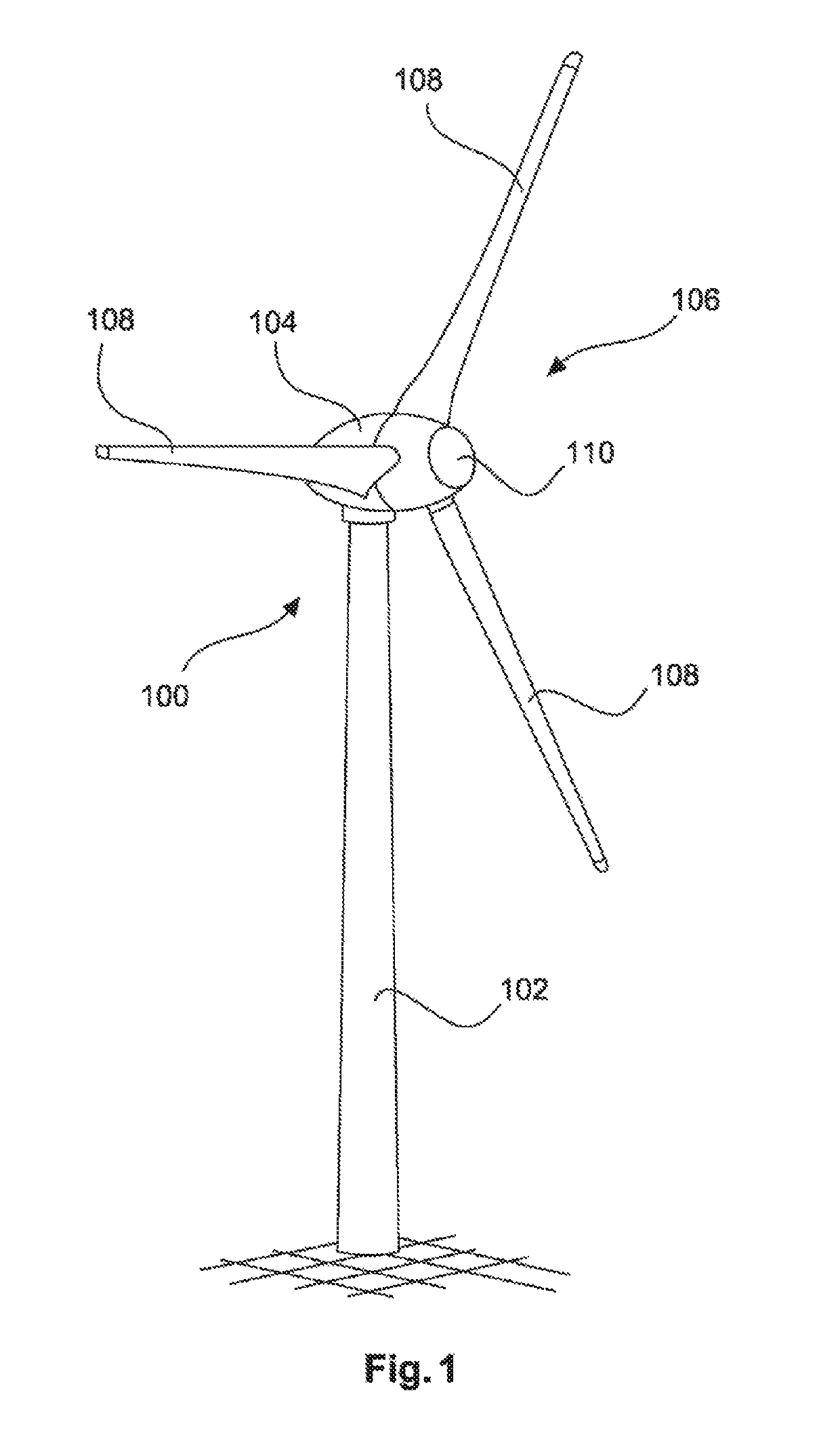
[0050]FIG. 1 shows a wind turbine 100 comprising a tower 102 and a nacelle 104. Arranged on the nacelle 104 is a rotor 106 with three rotor blades 108 and a spinner 110. During operation, the rotor 106 is set in a rotating motion by the wind and thereby drives a generator in the nacelle 104.

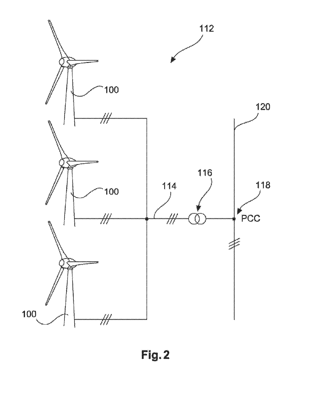
[0051]FIG. 2 shows a wind farm 112 comprising by way of example three wind turbines 100, which may be identical or different. The three wind turbines 100 are consequently representative of in principle any number of wind turbines of a wind farm 112. The wind turbines 100 provide their power, that is in particular the electricity generated, by way of an electrical farm system 114. In this case, the respectively generated electricity or power of the individual wind turbines 100 is added together and there is usually a transformer 116, which steps up the voltage in the farm to then feed it into the supply grid 120 at the feeding-in point 118, which is also generally referred to as the PCC. FIG. 2 is...


PUM


Abstract

A method for operating a plurality of wind energy installations configured for supplying electric power to an electrical supply system, that each have an aerodynamic rotor with rotor blades and an electrical generator and also operating equipment, is disclosed. The wind energy installations are operated while they are not connected to the electrical supply system, where at least one of the wind energy installations produces electric power and inputs the electric power into a local DC voltage system that connects the wind energy installations if the at least one of the wind energy installations currently produces more power than needed for supplying its own operating equipment. Additionally or alternatively, the operating equipment is supplied totally or in part with power from the local DC voltage system if the at least one of the wind energy installations currently produces less power than needed for supplying its operating equipment.

Description

BACKGROUNDTechnical Field[0001]The present invention relates to a method for operating multiple wind turbines, in particular a method for operating a wind farm. The present invention also relates to a collection of multiple wind turbines, in particular a wind farm. The present invention also relates to a wind turbine and to a method for operating a wind turbine.Description of the Related Art[0002]Wind turbines are known; they generate electrical energy from wind and feed it into an electrical supply grid. Some of the energy they need themselves for operating their operating devices. This includes, partly also depending on the type of wind turbine, operating yaw drives for directing the wind turbine into the wind, operating pitch drives for changing an angle of attack of the rotor blades in relation to the wind, supplying the generator with exciting power and also operating heating devices, such as for example for heating the rotor blades, and also electrically supplying the control ...

Claims


Application Information

Patent Timeline
Patent Type & Authority Patents(United States)
IPC IPC(8): F03D7/02H02J3/32H02P9/02H02J11/00H02K7/18F03D9/12F03D7/04F03D9/22F03D9/11F03D9/25H02P101/15
CPCH02J11/00F03D7/026F03D7/0224F03D7/0268F03D7/0276F03D7/048F03D9/11F03D9/12F03D9/22F03D9/257H02J3/32H02K7/183H02P9/02F05B2260/20F05B2260/42F05B2260/421F05B2260/85F05B2260/95F05B2270/111F05B2270/32F05B2270/323F05B2270/337H02P2101/15Y02E10/723Y02P90/50Y02T50/675F03D9/00Y02E60/16Y02E10/76Y02E10/72Y02T50/60Y02E70/30
Inventor BEEKMANN, ALFRED
Owner WOBBEN PROPERTIES GMBH
Learn More