
Cell culture device

a cell culture and device technology, applied in biomass after-treatment, specific use bioreactors/fermenters, biochemistry apparatus and processes, etc., can solve the problems of difficult to reduce equipment equipment cost considerably, large-scale cell cultivation requires enormous manpower and equipment costs, and the risk of contamination from the outside cannot be eliminated. , to achieve the effect of simple structure, easy attachment and detachability, and reduced cost of the culture vessel

Inactive Publication Date: 2019-04-23
HITACHI HIGH-TECH CORP
View PDF11 Cites 0 Cited by
  • Summary
  • Abstract
  • Description
  • Claims
  • Application Information

AI Technical Summary

Benefits of technology

The invention provides a simple and cost-effective culture vessel that can be easily attached and detached, which helps to simplify the process of culturing microorganisms.

Problems solved by technology

Therefore, large-scale cell cultivation requires enormous cost of manpower and considerable cost of equipment, which have been enormous obstacles to industrialization.
However, because the culture operations include operations in which the inside of the culture vessel is opened, such as the change of the culture medium in which the cover of the culture vessel is opened, the risk of contamination from the outside cannot be eliminated.
Therefore, the whole system including the robot has to be placed in a large-scale clean room, and it is difficult to reduce the cost of equipment considerably.
On the other hand, a closed culture system is restricted in the handling of liquid delivery; for example, a liquid should be sent by a liquid-driving force from the outside of the system.
Therefore, the handling requires ingenuity.

Method used


Image

  • Cell culture device
  • Cell culture device
  • Cell culture device

Examples


example 1

[0017]An Example is explained below using drawings.

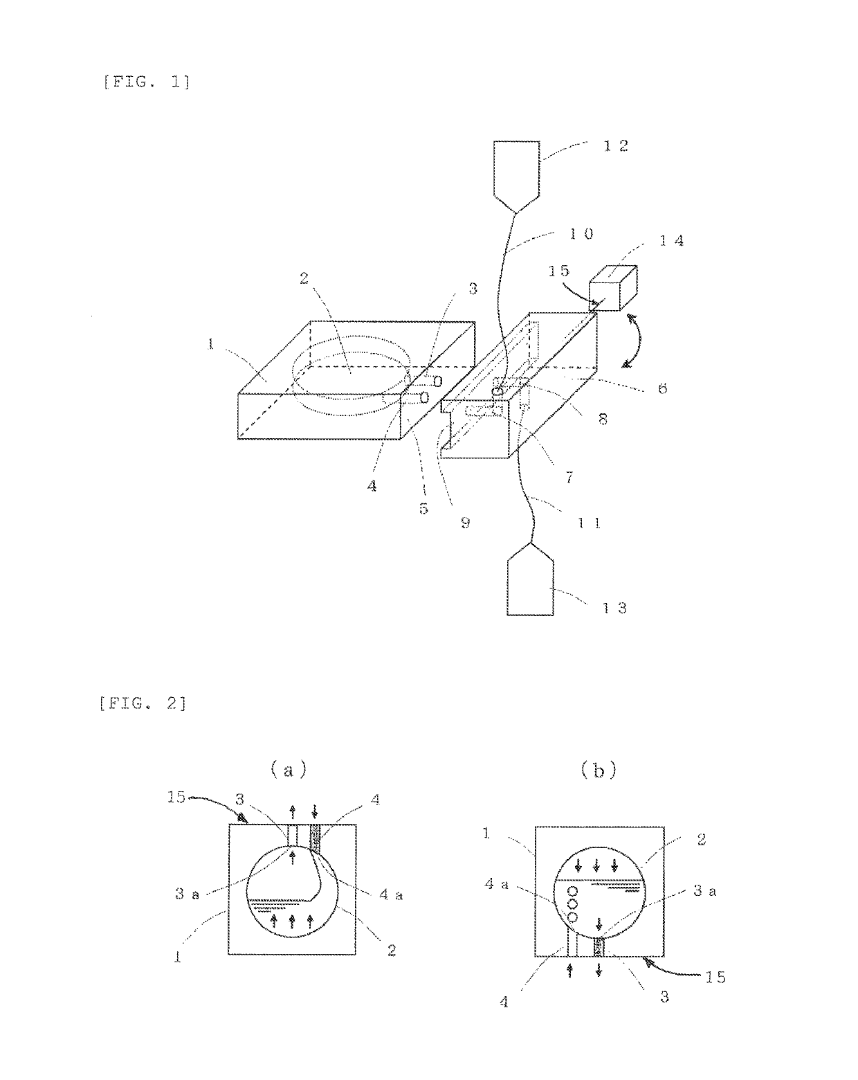
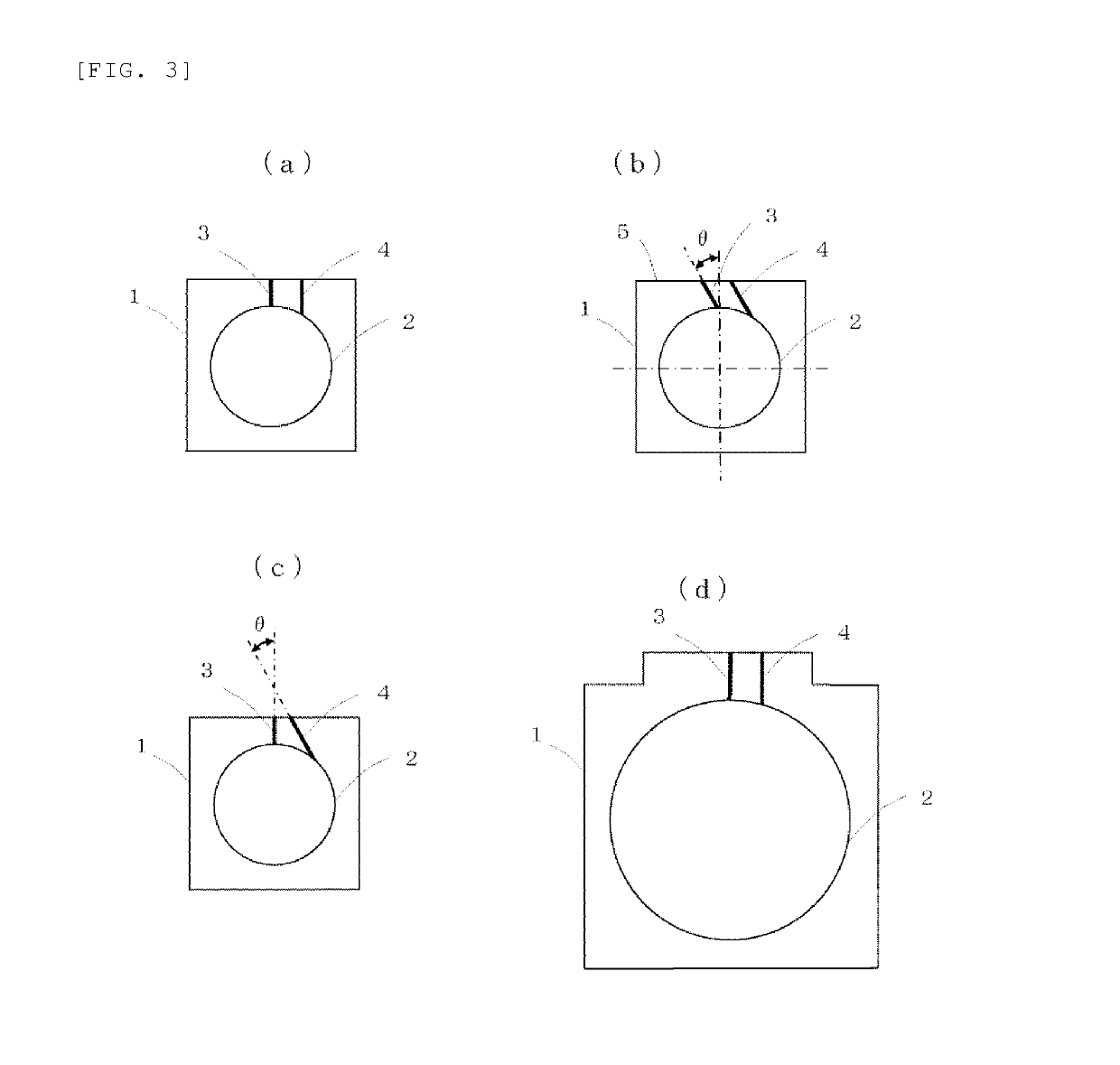
[0018]FIG. 1 is a schematic explanatory figure of the cell culture device according to the invention. A culture vessel 1 has a structure having a culture chamber 2, an intake flow path 4, a discharge flow path 3 and a connection portion 5. The discharge flow path 3 extends along the normal line to the culture plane of the culture chamber 2 to the connection portion 5. The intake flow path 4 is disposed right next to the discharge flow path 3 and parallel to the discharge flow path 3 and joins the culture chamber 2 and the connection portion 5. The space in the culture chamber 2 is closed when the intake flow path 4 and the discharge flow path 3 are closed. However, a part of the wall of the culture chamber 2 is made of a gas-permeable membrane, which allows gases to be exchanged while maintaining the closed system in the culture chamber 2.

[0019]The culture vessel 1 is connected to a supply source of a liquid and a part to which a li...

example 2

[0033]In the following Example, an example of cell cultivation using the culture vessels of the invention is described.

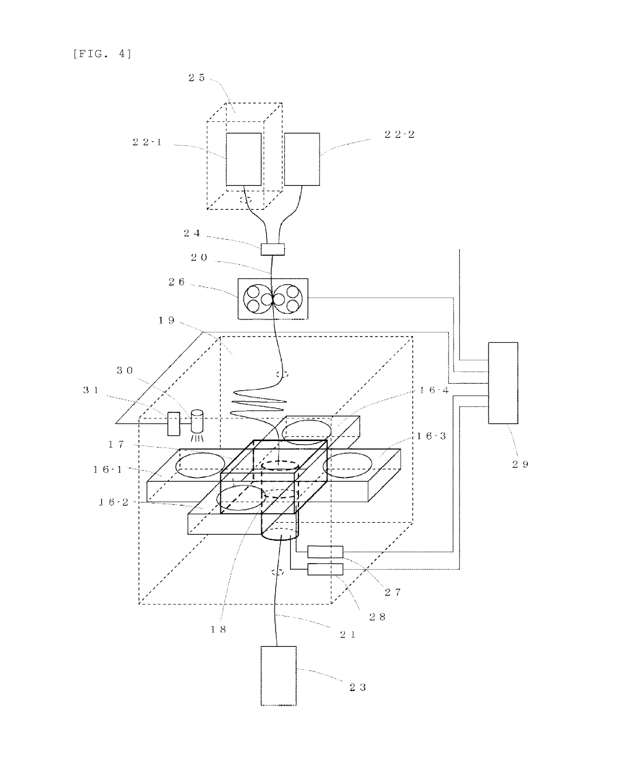
[0034]In FIG. 4, four culture vessels (16-1 to 16-4) are connected to a connection member 17 having four ports. A flow path-switching member 18 is included in the connection member 17 and enables a liquid to be sent to an optional culture vessel. These members including the culture vessels are disposed as a unit in an incubator 19. The environment in the incubator is set according to the type of cultivation. For example, environment settings at a temperature of 37 degrees, a humidity of 95% and a CO2 concentration of 5% are often used.

[0035]Tubes 20 and 21 are connected to an upstream part and a downstream part of the connection member 17. The tubes 20 and 21 are connected also to supply bags 22-1 and 22-2 and a recovery bag 23, respectively. A closed culture system is thus formed.

[0036]A plurality of supply bags may be provided. A supply bag 22-1 in which a culture...


PUM

PropertyMeasurementUnit
angleaaaaaaaaaa
humidityaaaaaaaaaa
humidityaaaaaaaaaa

Abstract

According to the present invention, a simple structure can be used to achieve reliable liquid delivery with no residual air, and simple attachment / detachment of a culture vessel, and thus a closed-system cell culture device exhibiting high reliability can be constructed at low cost. In the present invention, a liquid is supplied or discharged while a culture vessel is in an inclined state. The culture vessel is provided with two flow paths, namely an intake flow path and a discharge flow path, which connect a culture chamber and a connection member. Points where the flow paths join with the culture chamber are respectively configured as an intake port and a discharge port. The discharge port is provided in the position nearest to the axis of inclination of the culture vessel. The intake port is provided in a plane projected from a vertical plane including the aforementioned axis of inclination.

Description

TECHNICAL FIELD[0001]The present invention relates to a cell culture device for culturing cells using a culture vessel.BACKGROUND ART[0002]Processes in the cultivation of cells have been conducted by a skilled operator manually in a clean room which is sterilized as much as possible by strict production steps. Therefore, large-scale cell cultivation requires enormous cost of manpower and considerable cost of equipment, which have been enormous obstacles to industrialization.[0003]It is possible to automate a series of manual culture operations using a robot and to reduce the cost of manpower. However, because the culture operations include operations in which the inside of the culture vessel is opened, such as the change of the culture medium in which the cover of the culture vessel is opened, the risk of contamination from the outside cannot be eliminated. Therefore, the whole system including the robot has to be placed in a large-scale clean room, and it is difficult to reduce the...

Claims


Application Information

Patent Timeline
Patent Type & Authority Patents(United States)
IPC IPC(8): C12M1/00C12M3/06
CPCC12M23/40C12M23/50C12M27/16C12M29/00
Inventor SHIMASE, AKIHIROIMAI, KAZUMICHITAKADA, EIICHIROASO, SADAMITSU
Owner HITACHI HIGH-TECH CORP
Learn More