High frequency discharge ignition device
a high-frequency energy conductor and ignition device technology, applied in the direction of spark plugs, machines/engines, mechanical equipment, etc., can solve the problems of difficult to generate spark discharge for initiating combustion, occurrence of a decrease in startability or combustibility, and the difficulty of generating spark discharge, so as to reduce the influence of peripheral devices and shorten the high-frequency energy conductors
- Summary
- Abstract
- Description
- Claims
- Application Information
AI Technical Summary
Benefits of technology
Problems solved by technology
Method used
Image
Examples
first embodiment
[0020
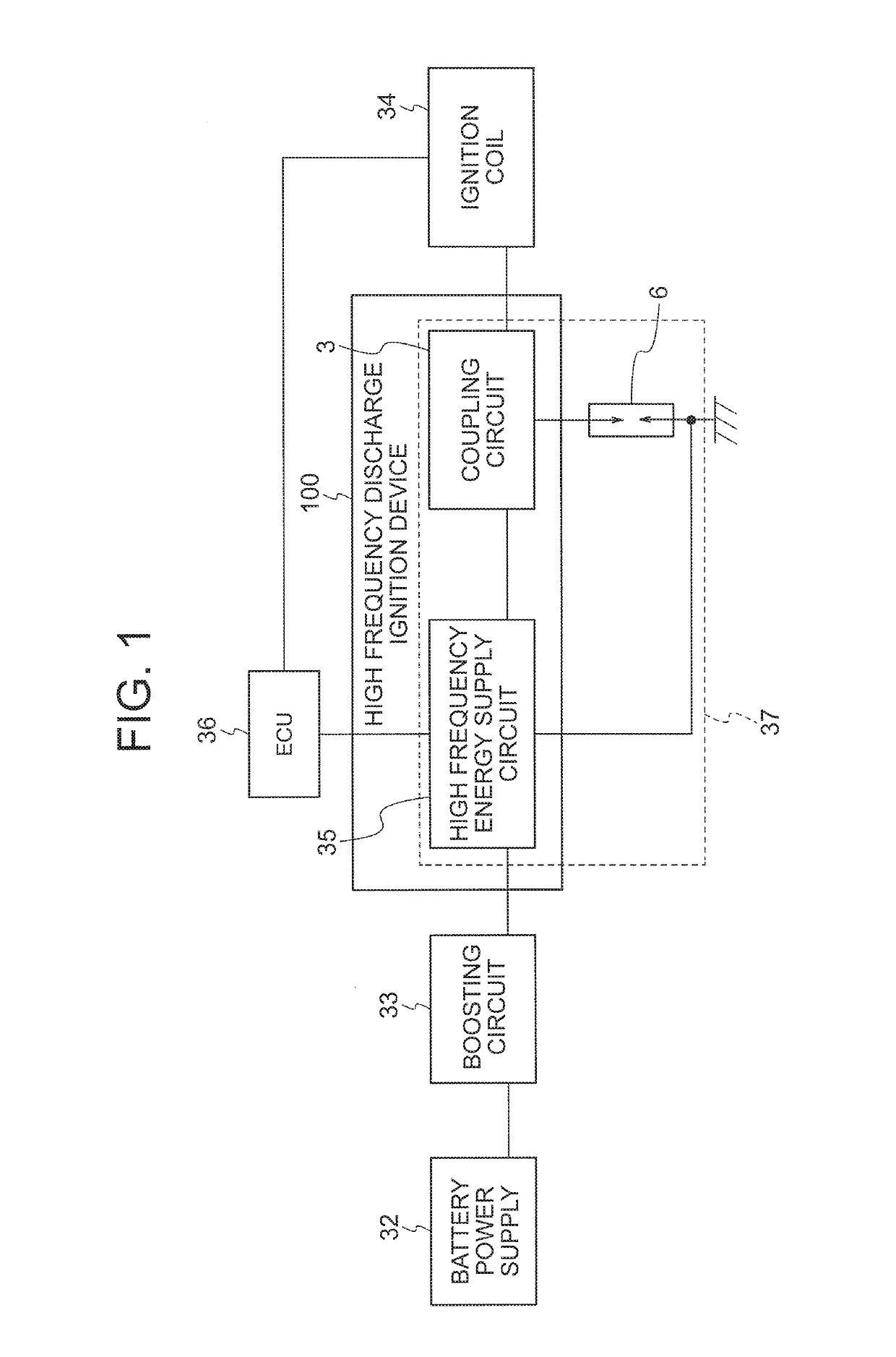
[0021]FIG. 1 is a block diagram showing a circuit configuration of a high frequency discharge ignition device 100 and peripheral devices thereof according to a first embodiment. The high frequency discharge ignition device 100 is constituted by a high frequency energy supply circuit 35 and a coupling circuit 3. The high frequency energy supply circuit 35 generates high frequency energy using the voltage of a battery power supply 32 having been boosted by a boosting circuit 33 as a power supply. The generated high frequency energy and a high voltage pulse supplied from an ignition coil 34 are coupled by the coupling circuit 3 and supplied to a spark plug 6. Drive control of each circuit is performed by an ECU 36. A loop 37 through which high frequency energy conducts is formed by the high frequency energy supply circuit 35, the coupling circuit 3 and the spark plug 6.
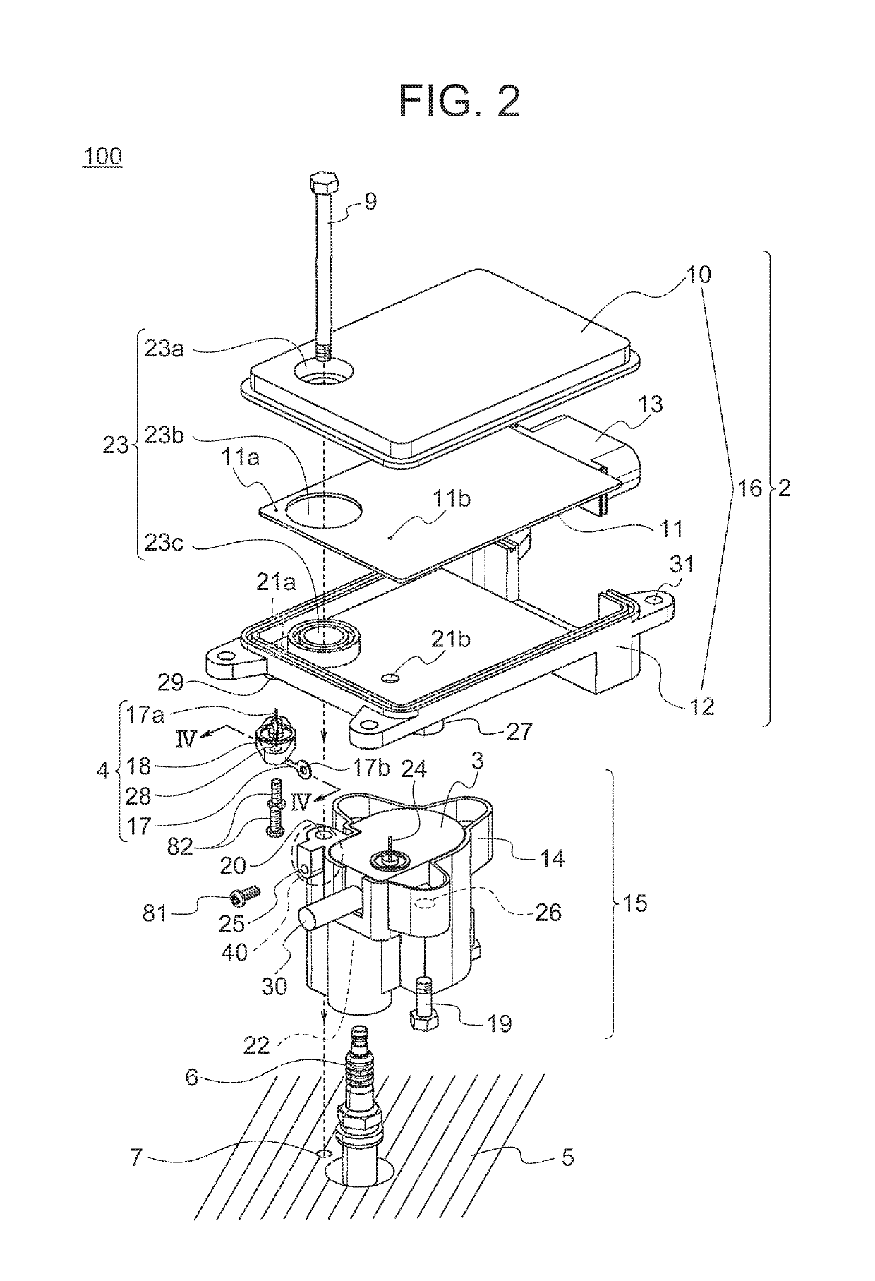
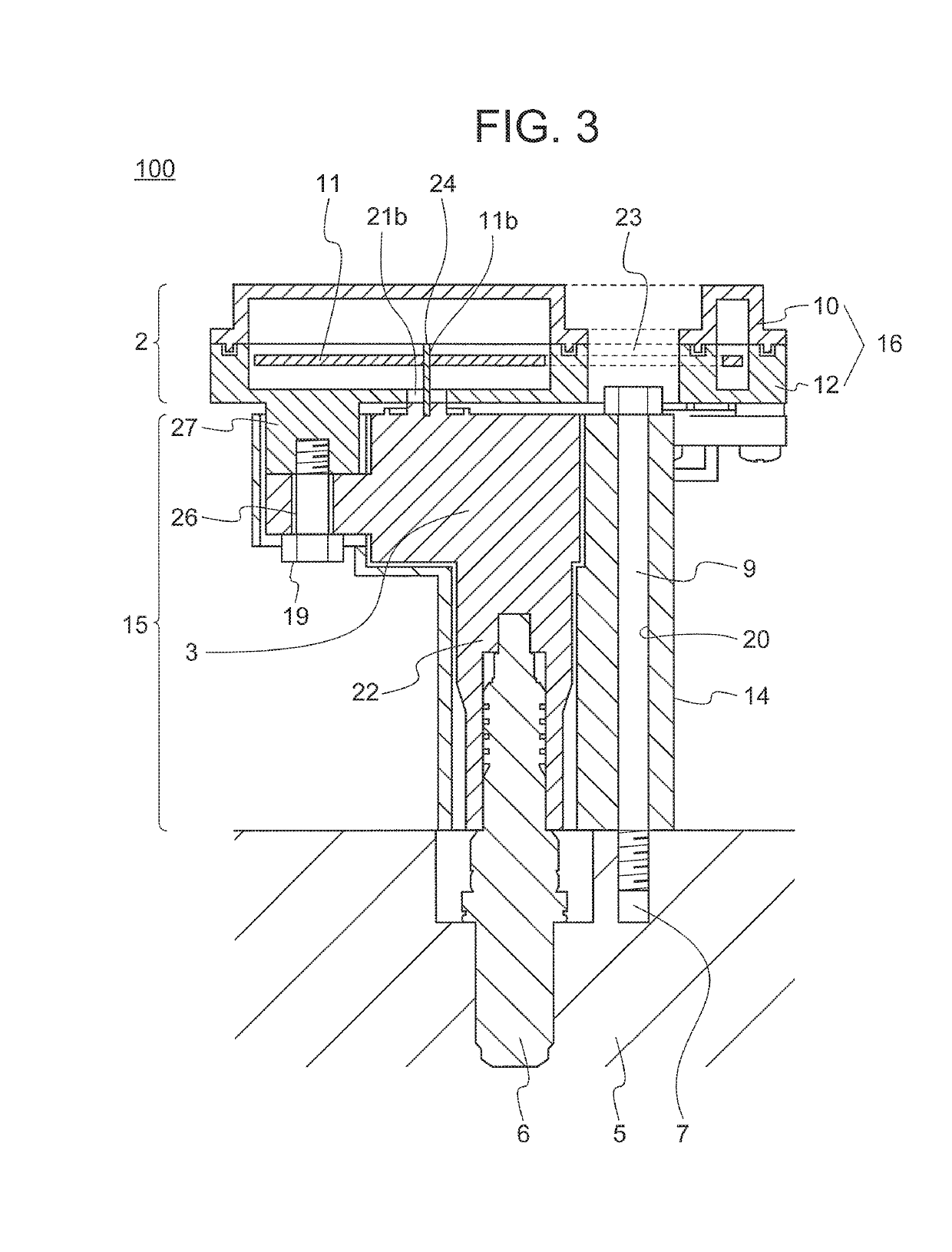
[0022]Components of the high frequency discharge ignition device 100 will be described hereinafter using FIG. 2 t...
second embodiment
[0058
[0059]Next, a high frequency discharge ignition device 110 according to a second embodiment will be described using FIG. 6. The shape of a connecting member of a terminal ASSY 4 is different from that of the first embodiment.
[0060]FIG. 6 is a broken-down perspective view showing an internal structure of the high frequency discharge ignition device 110. As shown in FIG. 6, a connecting member 170 of the terminal ASSY 4 is U-shaped and has, at one end thereof, a second connecting portion 17c which is provided with a screw terminal having a hole that passes therethrough in the vertical direction. The second connecting portion 17c is electrically connected to the bolt 9 by being sandwiched between the bolt 9 and the first housing 14.
[0061]As indicated above, in the high frequency discharge ignition device 110 according to the second embodiment, the connecting member 170 is electrically connected to the bolt 9 by being sandwiched between the bolt 9 and the first housing 14.
[0062]As ...
third embodiment
[0064
[0065]Next, a high frequency discharge ignition device 111 according to a third embodiment will be described using FIG. 7. In the first embodiment, the conducting member is a hexagonal bolt, however, in the third embodiment, the shape of the bolt differs from that in the first embodiment and is a hexagonal socket head bolt.
[0066]When the conducting member is a hexagonal bolt, as in the first embodiment, the diameter of a socket wrench for tightening the bolt 9 is larger than the diameter of the head of the bolt 9. Therefore, when also taking into account an operating range of the socket wrench, the diameter of the space 23 in the second housing 16 through which the socket wrench is inserted must be sufficiently larger than the diameter of the bolt 9.
[0067]On the other hand, when the conducting member is a hexagonal socket head bolt 90 as in the third embodiment, the diameter of a hexagonal wrench for tightening the hexagonal socket head bolt 90 is smaller than the diameter of t...
PUM
 Abstract
Description
Claims
Application Information
 - R&D
- Intellectual Property
- Life Sciences
- Materials
- Tech Scout
- Unparalleled Data Quality
- Higher Quality Content
- 60% Fewer Hallucinations
Browse by: Latest US Patents, China's latest patents, Technical Efficacy Thesaurus, Application Domain, Technology Topic, Popular Technical Reports.
© 2025 PatSnap. All rights reserved.Legal|Privacy policy|Modern Slavery Act Transparency Statement|Sitemap|About US| Contact US: help@patsnap.com


