Rolling vortex wing slat system and method of use

a technology of wing slats and vortex wings, which is applied in the direction of airflow influencers, influencers by generating vortices, drag reduction, etc., can solve the problems of loss of lift or stall condition, loss of control incident,

Inactive Publication Date: 2019-04-16
LAWRENCE JAMES RANDOLPH
View PDF17 Cites 8 Cited by
  • Summary
  • Abstract
  • Description
  • Claims
  • Application Information

AI Technical Summary

Problems solved by technology

One common problem associated with airfoils is the disruption of airflow around the airfoils from the upper surface of the airfoil at low airspeeds and at a high angle of attack resulting in a loss of lift or stall condition.
A stall condition can lead to a loss of control incident.

Method used


Image

  • Rolling vortex wing slat system and method of use
  • Rolling vortex wing slat system and method of use
  • Rolling vortex wing slat system and method of use

Examples


Embodiment Construction

[0012]Illustrative embodiments of the system and method of use of the present application are provided below. It will of course be appreciated that in the development of any actual embodiment, numerous implementation-specific decisions will be made to achieve the developer's specific goals, which will vary from one implementation to another. Moreover, it will be appreciated that such a development effort might be complex and time-consuming, but would nevertheless be a routine undertaking for those of ordinary skill in the art having the benefit of this disclosure.

[0013]The system and method of use will be understood, both as to its structure and operation, from the accompanying drawings, taken in conjunction with the accompanying description. Several embodiments of the system are presented herein. It should be understood that various components, parts, and features of the different embodiments may be combined together and / or interchanged with one another, all of which are within the...


PUM


Abstract

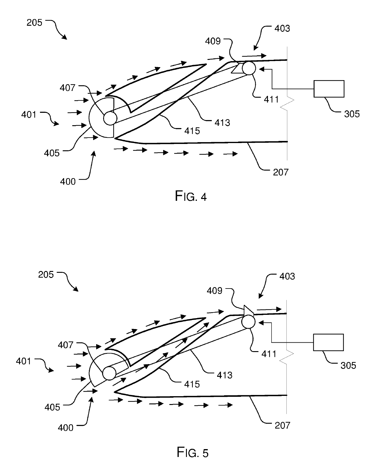
An aircraft includes an elongated wing having a leading edge extending to a trailing edge, an upper surface extending from the leading edge to the trailing edge, and a lower surface extending from the leading edge to the trailing edge; an air passage forming an entrance opening at the leading edge and configured to extend to an exit opening positioned at the upper surface; and an airflow stop configured to control airflow movement through the air passage.

Description

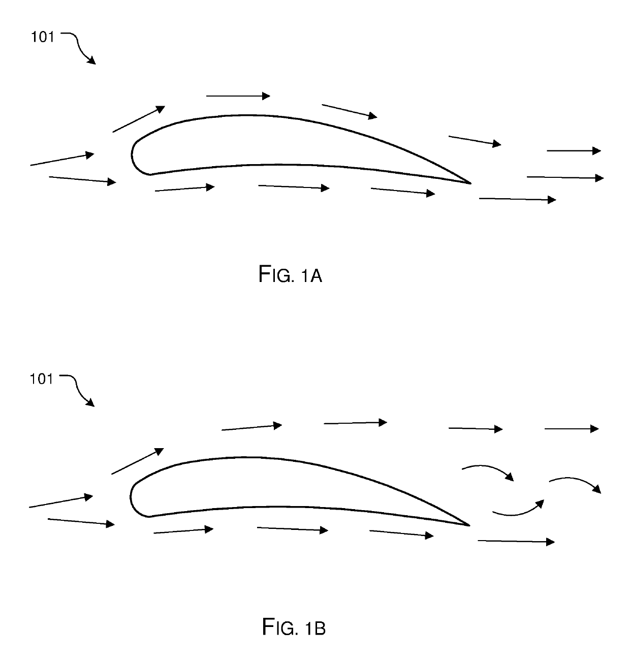
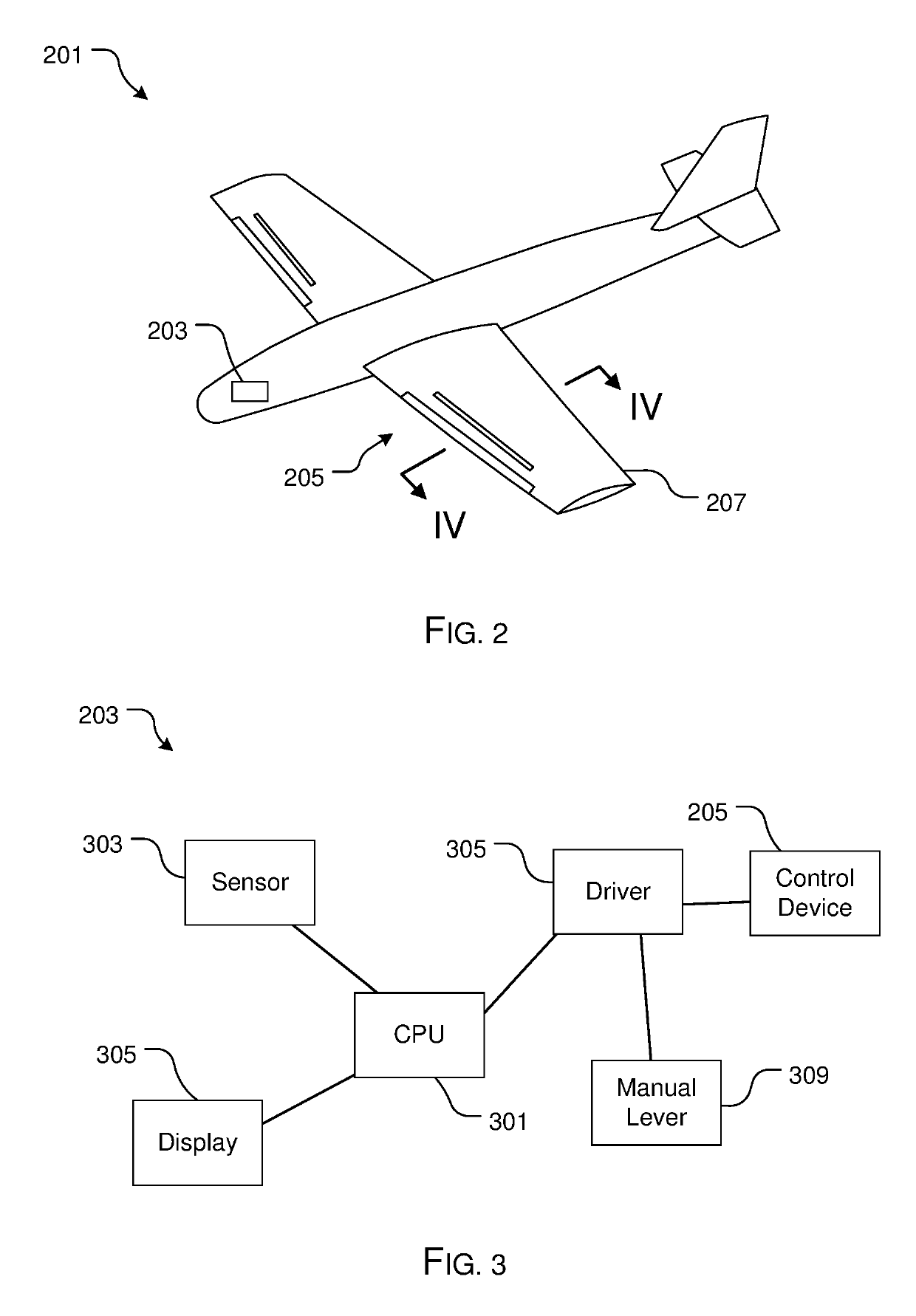
BACKGROUND1. Field of the Invention[0001]The present invention relates generally to systems and methods for controlling flow over an airfoil.2. Description of Related Art[0002]Aircraft airfoils are well known in the art and are effective means to create lift. For example, FIGS. 1A and 1B depict a simplified cross-sectional view of a conventional airfoil 101 having reduced and increased pressure surfaces that extend from the leading to the trailing edges of the body. A plurality of arrows is utilized to depict the airflow around the airfoil, which in FIG. 1B is shown separated at the trailing edge.[0003]One common problem associated with airfoils is the disruption of airflow around the airfoils from the upper surface of the airfoil at low airspeeds and at a high angle of attack resulting in a loss of lift or stall condition. A stall condition can lead to a loss of control incident.[0004]Accordingly, there is a need to actively manipulate airflow around the airfoil at low airspeeds wh...

Claims


Application Information

Patent Timeline
Patent Type & Authority Patents(United States)
IPC IPC(8): B64C21/08B64C23/06
CPCB64C21/08B64C23/06B64C9/24B64C2230/06B64C2230/20Y02T50/10
Inventor LAWRENCE, JAMES RANDOLPH
Owner LAWRENCE JAMES RANDOLPH
Why Eureka
Try Eureka