Stacking modular instrument system

a modular instrument and bus technology, applied in the field of measuring instruments, can solve the problems of serious affecting equipment research, development and upgrading, waste, inconvenience in equipment testing and maintenance, etc., and achieve the effect of reducing development time and design cost, and facilitating the update of the instrument bus system

Active Publication Date: 2019-03-19
ZHEJIANG UNIV
View PDF7 Cites 0 Cited by
  • Summary
  • Abstract
  • Description
  • Claims
  • Application Information

AI Technical Summary

Benefits of technology

[0005]To overcome drawbacks of existing backboard chassis type modular instruments such as poor extensibility and low flexibility, the present invention provides a stacking modular instrument bus device for truly flexibly configuring the modular instrument.
[0007]The N instrument sub-modules are connected with each other in series through the N−1 customized bus connectors to form an instrument sub-system. One end of the instrument sub-system is connected with the first bus termination module through one customized bus connector, and the other end thereof is connected with the second bus termination module through another customized bus connector. The customized bus connectors are able to be detached from the instrument sub-modules, the first bus termination module and the second bus termination module, thus achieving separation and reorganization among the instrument sub-modules, which is more flexible.
[0025]Preferably, every customized bus connector is a PCB, the PCB has two gold finger structures respectively at two ends thereof, the two gold finger structures are able to be inserted into the first module bus adapter, the second module bus adapter, the first termination bus adapter and the second termination bus adapter, so as to electrically connect the stacking modular instrument buses. Every customized bus connector has an ability of transmitting high-speed digital signals, which ensures signal integrity and power integrity of the stacking modular instrument buses. Every customized bus connector is coated with an insulating wear-resistant resin material for protection.
[0031]The present invention has beneficial effects as follows. The stacking modular instrument bus device, provided by the present invention, can freely stack and combine all the instrument sub-modules in the manner of building blocks, which is divorced from the conventional backboard type structure and becomes more flexible. Every instrument sub-module has the independent and complete instrument structure, and forms the system itself. The bus unit of every instrument sub-module is detached from the functional unit of the corresponding instrument sub-module. The present invention adopts the independent single-board design, which is more conducive to update the instrument bus system, thus saving the development time and design cost.

Problems solved by technology

With the increasing complexity of test tasks (such as ground simulation test systems and radar test systems of warships, spacecrafts and missiles), each test often requires a variety of instruments to work together.
Therefore, most of these measurements need a dedicated test system; and however, the currently developed test systems have a high degree of customization and poor adaptability, when test objects and even the models of the test objects change, the collaborative combination modes and the test protocols will change, so that the hardware and software of the instruments and the test systems need to be re-customized, which not only causes the serious waste, but also brings a lot of inconveniences to the equipment testing and maintenance, thereby seriously affecting the equipment research, development and upgrading.
For example, one simple instrument system only needs 2-3 instrument modules to complete the test task, and however, the existing chassis is a backboard chassis with ten card slots, the volume of the above simple instrument system is same as the volume of an instrument system comprising ten instrument modules, and is unable to be further decreased.

Method used


Image

  • Stacking modular instrument system
  • Stacking modular instrument system
  • Stacking modular instrument system

Examples


Embodiment Construction

[0038]To make the objects, technical solutions and advantages of the embodiments of the present invention more clearly, the technical solutions in the embodiments of the present invention will be described more clearly and completely with the accompanying drawings as follows. Obviously, the embodiments are part of the present invention, not all embodiments. According to embodiments of the present invention, other embodiments obtained by those of ordinary skill in the art without making creative work are within the scope of the present invention.

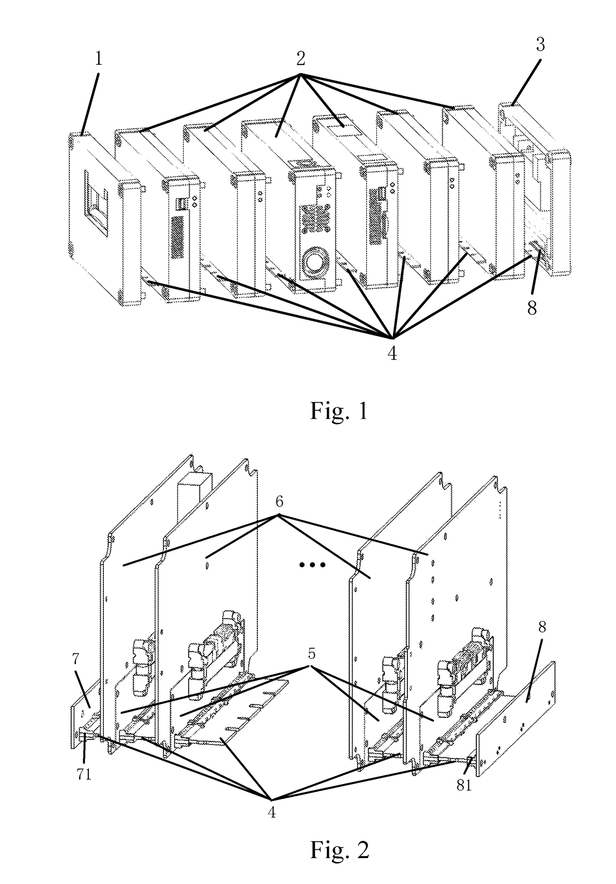
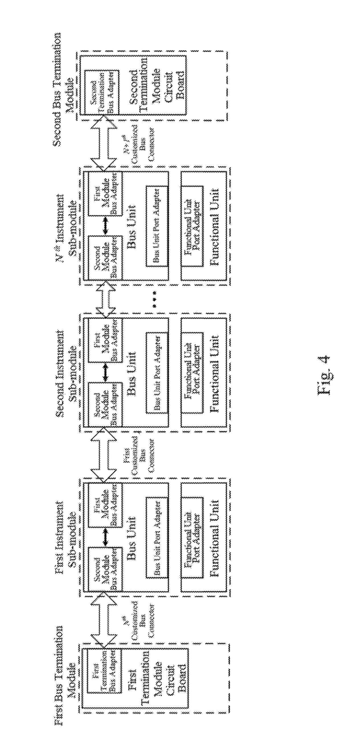
[0039]The present invention provides a stacking modular instrument bus device, which comprises N instrument sub-modules 2, N+1 customized bus connectors 4, a first bus termination module 1 and a second bus termination module 3, wherein N is a natural number.

[0040]As shown in FIG. 1, the N instrument sub-modules 2 are connected with each other in series through the N−1 customized bus connectors 4 to form an instrument sub-system. One end of th...


PUM


Abstract

A stacking modular instrument bus device includes N instrument sub-modules, N+1 customized bus connectors, a first bus termination module and a second bus termination module. The N instrument sub-modules are connected with each other in series through the N−1 customized bus connectors to form an instrument sub-system, two ends of the N instrument sub-modules are respectively connected with the first bus termination module and the second bus termination module through one customized bus connector; each of the instrument sub-modules includes a bus unit and a functional unit. The present invention can freely stack and combine all the instrument sub-modules in the manner of building blocks, which is divorced from the conventional backboard type structure and becomes more flexible. Every instrument sub-module has the independent and complete instrument structure and form the system itself. The bus unit of the instrument sub-module is detached from the functional unit thereof.

Description

CROSS REFERENCE OF RELATED APPLICATION[0001]This is a U.S. National Stage under 35 U.S.C 371 of the International Application PCT / CN2016 / 080862, filed May 3, 2016.BACKGROUND OF THE PRESENT INVENTIONField of Invention[0002]The present invention relates to the measuring instrument field, and more particularly to the field of the modular instrument bus device.Description of Related Arts[0003]With the increasing complexity of test tasks (such as ground simulation test systems and radar test systems of warships, spacecrafts and missiles), each test often requires a variety of instruments to work together. Therefore, most of these measurements need a dedicated test system; and however, the currently developed test systems have a high degree of customization and poor adaptability, when test objects and even the models of the test objects change, the collaborative combination modes and the test protocols will change, so that the hardware and software of the instruments and the test systems ...

Claims


Application Information

Patent Timeline
Patent Type & Authority Patents(United States)
IPC IPC(8): G06F13/40
CPCG06F13/4027G06F13/4095G06F13/40
Inventor YE, LINGYUNSUN, XINGLINLI, CAIXIASONG, KAICHEN
Owner ZHEJIANG UNIV
Why Eureka
Try Eureka