
Filters with echogenic characteristics

a filter and filter technology, applied in the field of filters, can solve the problems that the conventional use of echogenic materials has not kept pace with the advancement of imaging ultrasound applications, and achieve the effects of enhancing the echogenic characteristic of the portion of the filter, and enhancing the echogenic characteristic of the filter

Inactive Publication Date: 2019-03-05
VOLCANO CORP
View PDF1163 Cites 3 Cited by
  • Summary
  • Abstract
  • Description
  • Claims
  • Application Information

AI Technical Summary

Benefits of technology

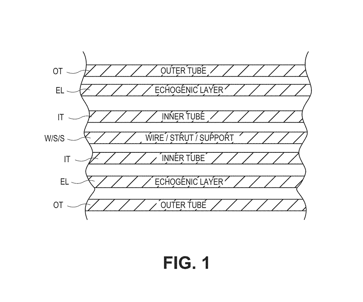
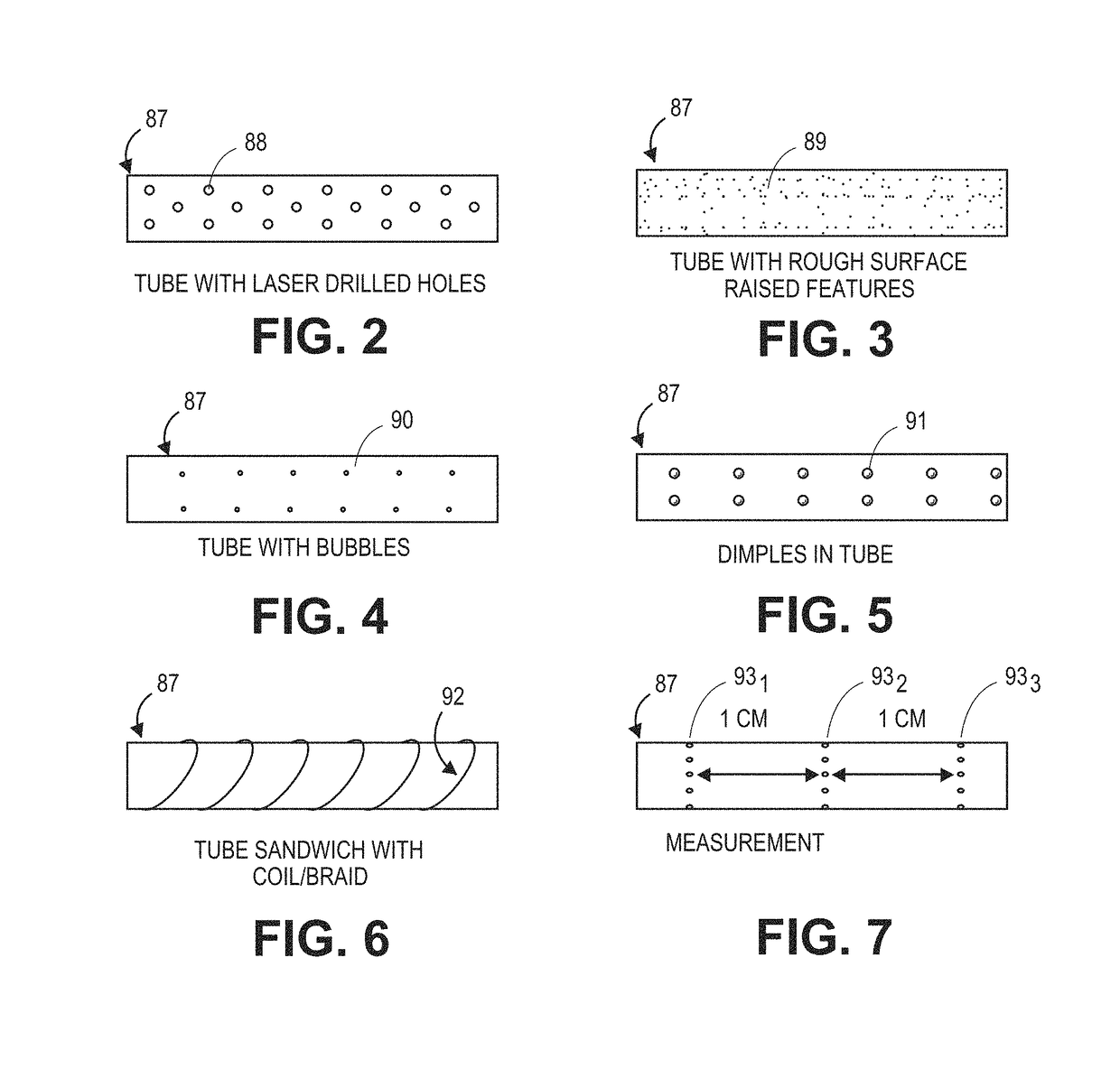
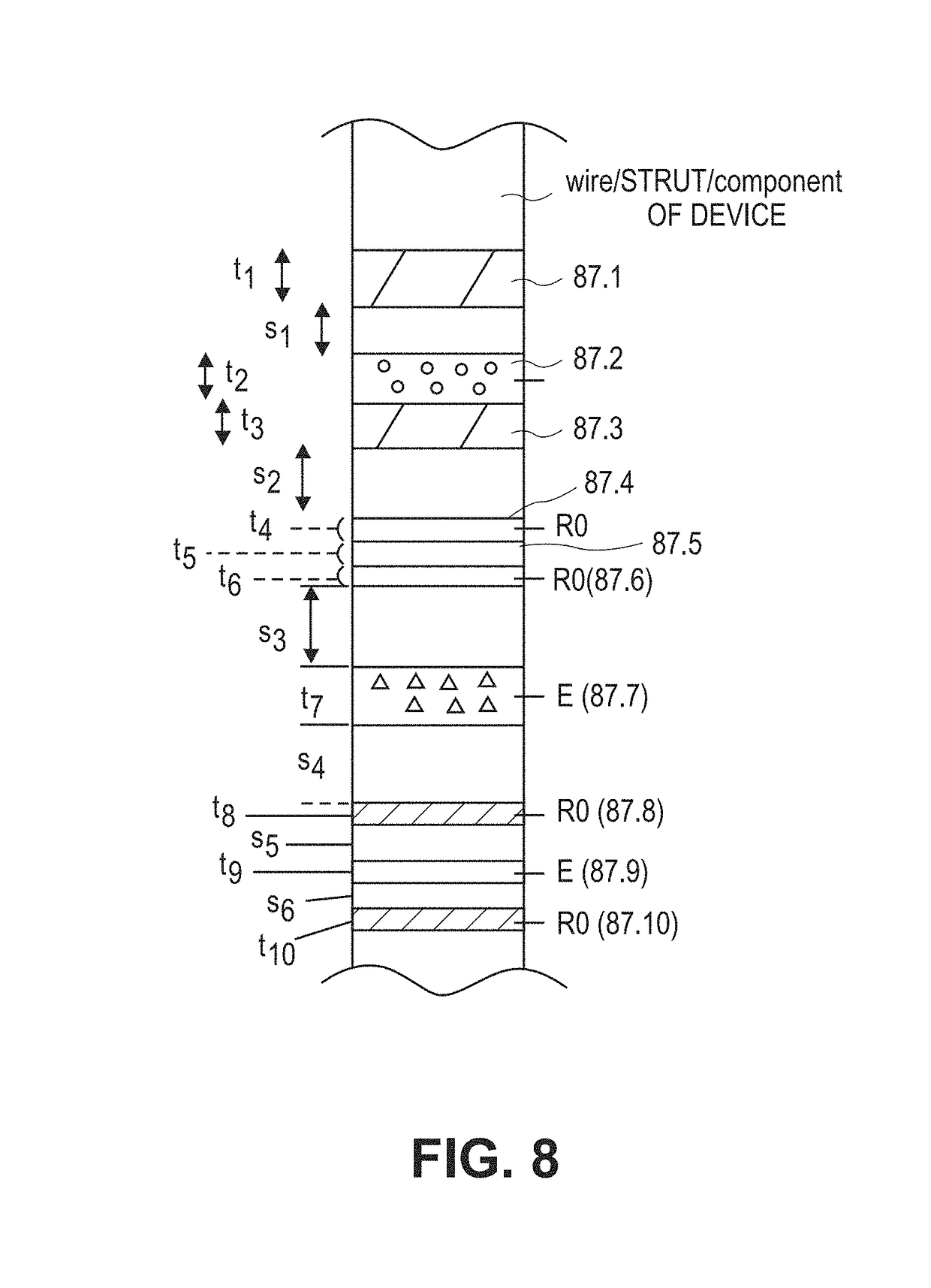
[0007]This and other embodiments include one or more of the following features. In one aspect, the modification can provide an enhanced echogenic characteristic of the filter is a modification to a portion of the filter to enhance the echogenic characteristics of that portion of the filter. In another aspect, the modification can provide an enhanced echogenic characteristic of the filter which can be the formation of dimples into a surface of the filter. In yet another aspect, the dimples can be of sufficient number and scaled to a suitable size, shape, orientation and pattern for use with an intravascular ultrasound system. In a further aspect, the modification can provide an enhanced echogenic characteristic of the filter which can be the formation of protrusions formed in, placed on or joined to a filter surface. In an additional aspect, the protrusions can be of sufficient number and scaled to a suitable size, shape, orientation and pattern for use with an intravascular ultrasound system. In another aspect, the modification can provide an enhanced echogenic characteristic of the filter including the roughening one or more surfaces of a filter. In yet another aspect, the roughening can be performed using a chemical process, a laser or bead blasting technique. In still a further aspect, the roughening can be of sufficient scale to a suitable size, shape, orientation and pattern for use with intravascular ultrasound systems. In a further aspect, the modification can provide an enhanced echogenic characteristic of the filter including altering one or more steps of a filter manufacturing technique to introduce cavities, voids or pockets to locally modify or adapt one or more acoustic reflection characteristics to improve echogenicity in one or more specific regions of the filter. In an additional aspect, the cavities, voids or pockets can be of sufficient number and scaled to a suitable size, shape, orientation and pattern for use with an intravascular ultrasound system.

Problems solved by technology

While echogenic materials have been described for some uses in medical devices, the conventional uses of echogenic materials has not kept pace with the advancements in applications for imaging ultrasound.

Method used


Image

  • Filters with echogenic characteristics
  • Filters with echogenic characteristics
  • Filters with echogenic characteristics

Examples


Embodiment Construction

[0051]Filters are more complex structures in contrast to the relatively simple designs found in catheters and needles. In a more complex device like a filter there is a need to identify specific portions within the device during some medical procedures. In addition, it would be advantageous as well to determine the orientation of the device including components within the device to one another (as used for determining deployment, retrieval and the various intermediate stages thereof) as well as the overall filter orientation to the surrounding lumen or vessel. In contrast to the conventional techniques using location of the tip or start or end of the entire length, a more complex structure such as a filter position, orientation or relative placement information would yield specific benefits. In some cases, aspects, portions or attributes of the overall filter or filter components or portions will enable more useful determinations about the filter in relation to the physiological env...


PUM


Abstract

There are described a variety of intravascular filters wherein at least a portion of the filter has been modified to provide an enhanced echogenic characteristic of the filter. Also described are systems for positioning a variety of intravascular filters within the vasculature wherein the systems include an intravascular filter, an intravascular ultrasound transducer, a user interface configured to receive input from an operator regarding a surgical procedure including an insertion site and a destination site for positioning the filter according to the surgical procedure, a display, and a processor. The filter can include a hub and a plurality of legs or wires or segments extending from the hub, wherein at least a portion of the hub or a portion of one or more of the legs or wires or segments is modified to provide an enhanced echogenic characteristic of the filter or a portion of the filter.

Description

CROSS REFERENCE TO RELATED APPLICATIONS[0001]This application is a continuation in part of U.S. patent application Ser. No. 14 / 776,518, filed on Sep. 14, 2015, which claims the benefit of International Application No. PCT / US2014 / 027259, filed Mar. 14, 2014, which claims priority to U.S. Provisional Patent Application No. 61 / 785,204, filed Mar. 14, 2013, each of which is herein incorporated by reference in its entirety. This application also claims priority to U.S. Provisional Application No. 62 / 054,876, filed on Sep. 24, 2014, which is herein incorporated by reference in its entirety.INCORPORATION BY REFERENCE[0002]All publications and patents and patent applications mentioned in this specification are herein incorporated by reference to the same extent as if each individual publication or patent or patent application was specifically and individually indicated to be incorporated by reference.FIELD[0003]Aspects of the invention described herein relate generally to filters inserted i...

Claims


Application Information

Patent Timeline
Patent Type & Authority Patents(United States)
IPC IPC(8): A61B8/00A61F2/01A61B8/08A61B8/12
CPCA61F2/01A61B8/0891A61B8/12A61F2002/011A61F2002/016A61F2220/0008A61F2250/0096A61F2230/0058A61F2230/0067A61F2230/0078A61F2230/0093A61F2240/001A61F2220/0016A61F2/0105A61F2/011
Inventor JOHNSON, ERICSTIGALL, JEREMY
Owner VOLCANO CORP
Learn More