
Method of mounting a flag holder mount onto a motorcycle

a technology for flag holders and motorcycles, applied in flags/banners, instruments, display means, etc., can solve problems such as inability to readily accept pad mounts, and achieve the effects of eliminating control problems, solid and stable foundations, and speeding up acceleration and travel of motorcycles without risking damage to the motorcycl

Active Publication Date: 2019-02-19
WILLIAMS JR ROY E
View PDF83 Cites 4 Cited by
  • Summary
  • Abstract
  • Description
  • Claims
  • Application Information

AI Technical Summary

Benefits of technology

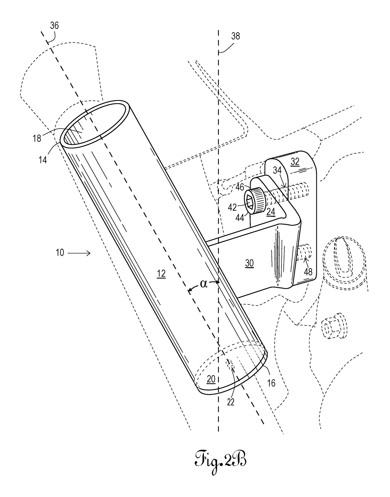
The present invention is a flag mount for motorcycles that can safely display flags at high speeds without damaging the motorcycle or interfering with visibility. The flag mount exhibits two angles when mounted to the motorcycle, including an angle away from the motorcycle (between 7° and 15°) and a back angle (between 5° and 15°). The angle of the flag mount allows for faster acceleration and travel of the motorcycle without risking damage to the motorcycle. The calculated design angles keep the flag hang away from the motorcycle during stops and full flag-waving operation. The present invention maintains the integrity and strength of the original equipment without any drilling or changes required to the user's motorcycle. The flag mount can be left attached either permanently or can be taken on and off as desired. The invention also enhances the look of the motorcycle.

Problems solved by technology

Other models of motorcycles exist, e.g., Harley-DavidsonHeritage Softail® FLS, XL and FX models, which cannot readily accept the pad mount due to configurational differences at the mounting point on the motorcycle.

Method used


Image

  • Method of mounting a flag holder mount onto a motorcycle
  • Method of mounting a flag holder mount onto a motorcycle
  • Method of mounting a flag holder mount onto a motorcycle

Examples


Embodiment Construction

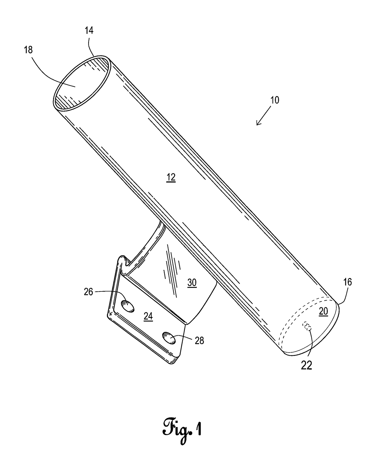
[0029]Referring now to FIG. 1, flag mount 10 is comprised of a flag holder or cylindrical main body 12 having end 14 and end 16. Cylindrical main body 12 is hollow and has an opening 18 at end 14. End cap 20 having drainage hole 22 is attached to end 16 of cylindrical main body 12. Pad mount 24 has apertures 26 and 28. Connecting bar 30 connects pad mount 24 to cylindrical main body 12 so as to comprise a single piece.

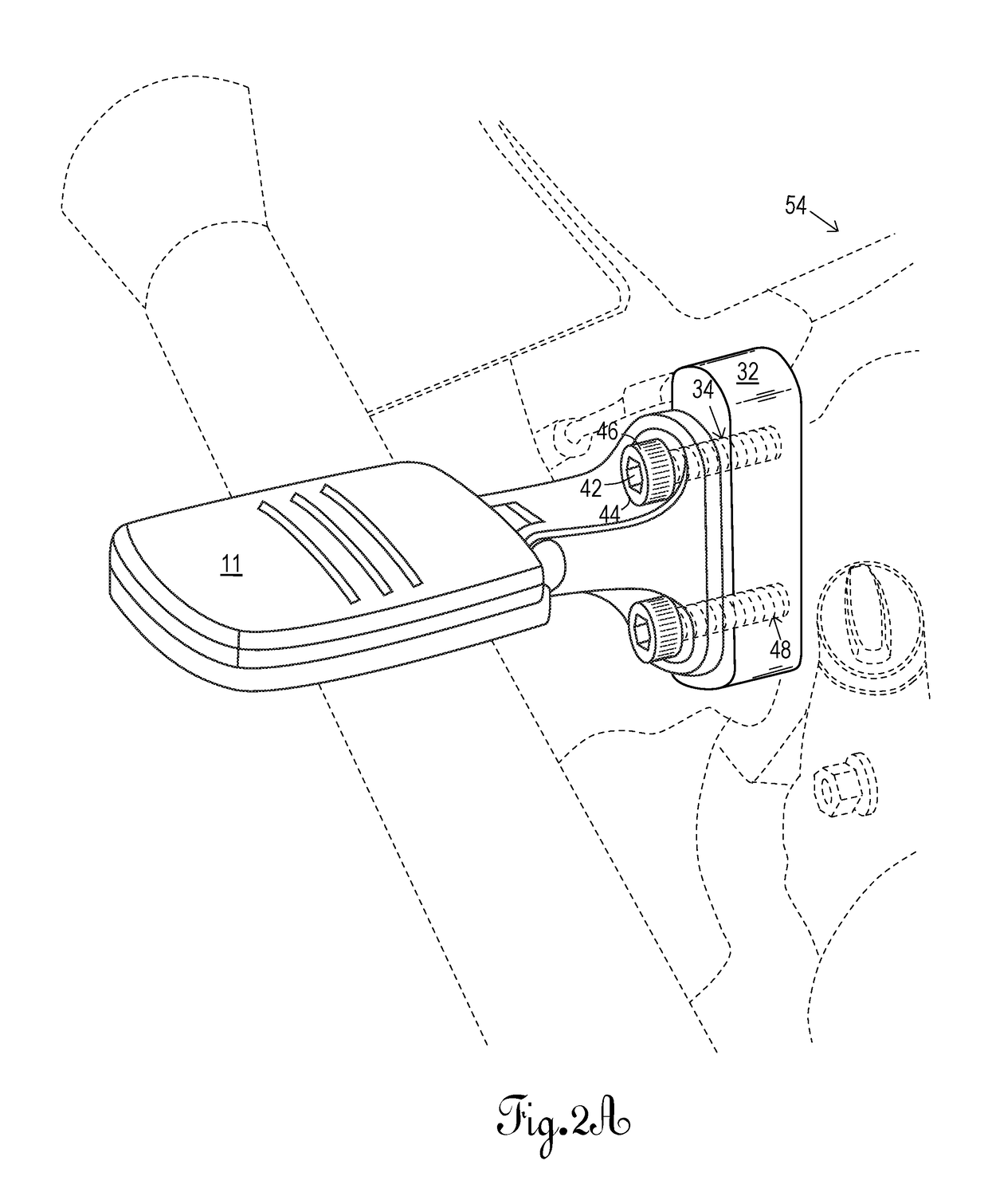
[0030]Referring now to FIG. 2A, passenger foot peg 11 is shown mounted to mounting block 32 on the right side of motorcycle 54. Passenger foot peg 11 is removed to allow installation of flag mount 10. Referring now to FIG. 2B, flag mount 10 is shown mounted to mounting block 32 on the right side of motorcycle 54. The installation of flag mount 10 occurs at the same location, i.e., mounting block 32, on motorcycle 54 where the passenger foot peg 11 is located. The passenger foot peg 11 is removed from mounting block 32 exposing threaded cavities 40a-40d (see FIG. 3).

[00...


PUM


Abstract

A flag holder mount comprising a hollow cylindrical main body, a pad mount and a connecting bar connecting the pad mount to the cylindrical main body so as to comprise a single piece. When mounted to the center of gravity portion of the frame of a motorcycle, the flag holder angles away from the motorcycle and angles back toward the rear of the motorcycle. In an alternative embodiment, the flag holder includes a post mount comprising a connector having a closed end and includes an aperture therein adapted to receive a pin or other comparable fastener to connect the connector of the post mount to the passenger foot peg support. In an alternative embodiment, the flag holder may have a pre-angled connector, or post mount, adapted to receive the pre-angled foot peg support extending from the frame of the motorcycle.

Description

CROSS REFERENCE TO RELATED APPLICATIONS[0001]None.STATEMENT REGARDING FEDERALLY SPONSORED RESEARCH OR DEVELOPMENT[0002]None.BACKGROUND OF THE INVENTION[0003]1. Field of the Invention[0004]This invention is related to a flag holder, and more particularly to a flag holder mount for holding at least one flag mounted to a motorcycle.[0005]2. Description of the Related Art[0006]Motorcycles—also called motorbikes or bikes—are traditionally two-wheeled motorized vehicles, but some models include three-wheeled versions called “trikes.” As used herein, the term “motorcycle” includes “trikes.” Motorcycle enthusiasts enjoy riding their motorcycles on any occasion. Several motorcycle enthusiasts are also very patriotic and want to show off their American flag. They regularly participate in riding groups and in parades where several of the motorcyclists proudly display and exhibit flags (e.g., patriotic and / or pertaining to their group affiliation) attached to their motorcycles as they travel do...

Claims


Application Information

Patent Timeline
Patent Type & Authority Patents(United States)
IPC IPC(8): G09F17/00
CPCG09F17/00G09F2017/0075G09F2017/0066
Inventor WILLIAMS, JR., ROY E.
Owner WILLIAMS JR ROY E
Learn More