Device for automatic inflation-deflation of a containment capacity for a pressurized gaseous fluid

a technology of containment capacity and automatic inflation, which is applied in the direction of tyre parts, tyre measurement, functional valve type, etc., can solve the problems of major drawbacks in the solution of providing sealing and water penetration into the inflation/deflation devi

Active Publication Date: 2019-02-05
TELEFLOW
View PDF14 Cites 0 Cited by
  • Summary
  • Abstract
  • Description
  • Claims
  • Application Information

AI Technical Summary

Benefits of technology

[0017]An object of the invention is thus to remedy at least the above-mentioned drawback by proposing a device for inflating / deflating a capacity that is protected from external atmospheric agents, and in which the noise generated by it operating is reduced so as no longer to be problematic.
[0018]Another object of the invention is to provide such a device that is of simple, safe, and rational design.
[0022]an elastically deformable washer mounted between the two portions and around the discharge orifice for protecting it from external atmospheric agents.
[0023]In accordance with the invention, and to provide optimum sealing, while also reducing the undesired noise due to the device operating, one of the portions is provided with arrangements for receiving the washer, which arrangements are suitable for allowing said washer to deform elastically, under the effect of a pressure of a gaseous fluid discharging through the discharge orifice, so as to release face-on bearing formed by an annular protuberance provided on the other portion, and so as to generate a fluid discharge passage between said annular protuberance and said washer.
[0024]In this way, while the confinement capacity is being deflated, i.e., while gaseous fluid is discharging via the discharge orifice, said fluid constrains the protective washer to deform elastically, and in particular to curve in the washer-receiving arrangements. In this way, the fluid under pressure can be discharged via a passage opened up between said washer and the annular projection. The term “curve” is used to mean that the surface of the washer, as defined between its inner perimeter and its outer perimeter, takes on a concave shape relative to the washer-receiving arrangements. Thus, the washer does not start vibrating and does not generate any undesired noise. In addition, during deflation, the movement of the washer consists solely in a curvature movement so that no portion of the washer comes to strike any portion of the device. The device is of simple, safe, and rational design.
[0026]The circumferential bearing on the inner and outer perimeters of the washer, combined with the pressure of the gaseous fluid, prevents to an even greater extent the washer from starting to vibrate and from generating undesired noise.

Problems solved by technology

Sprayed dust, mud, and water can penetrate into the inflation / deflation device and damage it.
However, that solution for providing the sealing suffers from a major drawback.

Method used


Image

  • Device for automatic inflation-deflation of a containment capacity for a pressurized gaseous fluid
  • Device for automatic inflation-deflation of a containment capacity for a pressurized gaseous fluid

Examples


Embodiment Construction

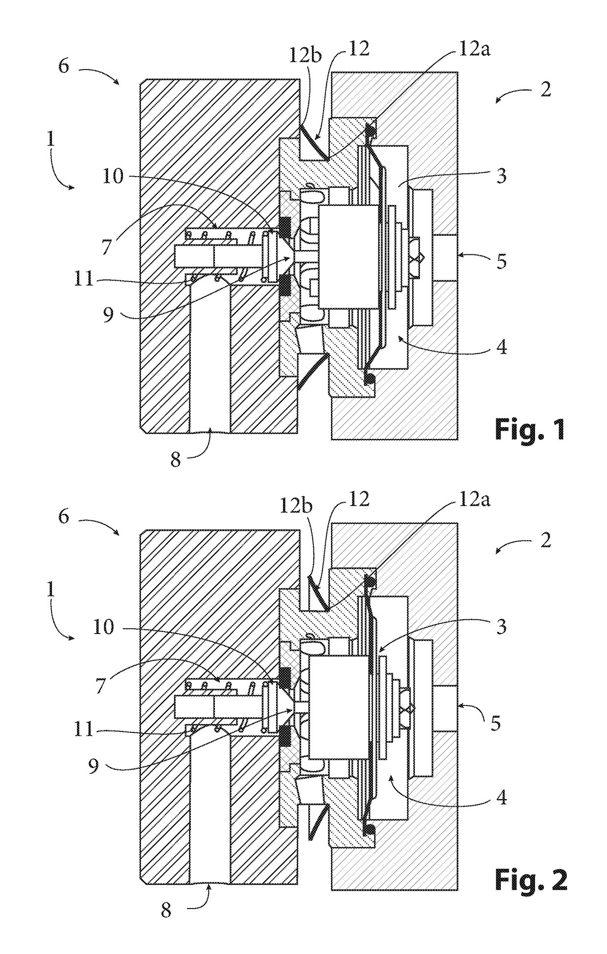
[0035]For reasons of simplification, the portions or elements that are found identically or similarly in the invention described below and in the state of the art shown in FIGS. 1 and 2 are identified by like numerical references.

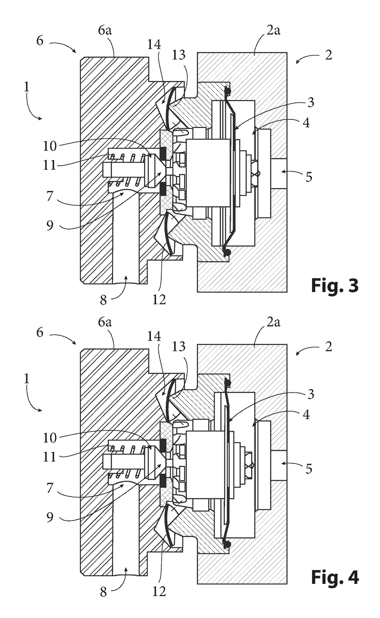
[0036]FIGS. 3 and 4 show, in longitudinal section, a pneumatic device 1 that is controlled and sealed for inflating / deflating a confinement capacity such as a tire of a wheel of a vehicle, for example. In well known manner, the device 1 is made up of two portions that define two chambers.

[0037]The first portion 2 is in the form of a hollow body 2a, e.g., a cylindrical hollow body. The first chamber 4 defined inside the hollow body 2a communicates with the outside of the device 1 via an intake orifice 5 provided in one of the circular bases of said cylindrical hollow body 2a. This intake orifice 5 is designed to receive injection means (not shown) for injecting a gaseous fluid under pressure, e.g., compressed air.

[0038]The first portion 2 includes a control ...


PUM


Abstract

Described herein is an inflation / deflation device of the type comprising a portion provided with an intake orifice for taking in a gaseous fluid under pressure, and a portion provided firstly with an inflation / deflation orifice designed to communicate with the confinement capacity, and secondly with a discharge orifice opening out between the two portions; and a valve member control system for inflation / deflation operations per se. In accordance with the invention, one of the portions is provided with arrangements for receiving a washer, which arrangements are suitable for allowing said washer to deform elastically, under the effect of a pressure of a gaseous fluid discharging through the discharge orifice, so as to release face-on bearing by an annular protuberance provided on the other portion, and so as to generate a fluid discharge passage between said annular protuberance and said washer.

Description

BACKGROUND[0001]Technical Field[0002]The present invention relates to the technical field of devices for automatically inflating / deflating a capacity, e.g., a pneumatic tire of a vehicle wheel, using a gaseous fluid under relative pressure.[0003]It is sometimes useful to be able to inflate or deflate the tires of the wheels of a vehicle remotely, so as to adapt the footprints and bearing capacities of said tires as a function of the state of the terrain over which the vehicle is moving.[0004]This applies in particular to all-terrain vehicles that must be capable of making progress under the best possible conditions, equally well when travelling over hard, stony, and soft terrain in succession, without the driver being forced to interrupt the progress to make an appropriate correction to the inflation pressures of the various tires manually and while the vehicle is at a standstill.[0005]This application is given merely by way of example because, in many fields, it is also useful or e...

Claims


Application Information

Patent Timeline
Patent Type & Authority Patents(United States)
IPC IPC(8): F16K15/20B60C23/00
CPCF16K15/202B60C23/003Y10T137/3646B60C23/00354B60C23/00363F16K15/10F16K31/126B60C23/00
Inventor FAZEKAS, STEPHANE
Owner TELEFLOW
Why Eureka
Try Eureka